Test C: Locks Do Not Operate
- Check fuse No. 11 (15-amp), fuse No. 12 (10-amp), and fuse No. 29 (15-amp) in instrument panel fuse block. Check all connections for clean tight fit. Check for loose or damaged wiring. If fuses and wiring are okay, go to next step. If fuse(s) are blown or wiring is faulty, replace or service as necessary and go to next step.
- Using New Generation Star (NGS) scan tester, retrieve continuous DTC's and perform on demand self test. See GENERIC ELECTRONIC MODULE (GEM)
article. If DTC B1342 is retrieved, replace GEM. If continuous and self test DTC B1318 is retrieved, service charging system to correct low-voltage condition. If self test DTC B1396 is retrieved, replace door switch shorted in LOCK position. If self test DTC B1397 is retrieved, replace door switch shorted in UNLOCK position. If no DTC's are retrieved, go to next step.
- Check fuse No. 37 (20-amp) in instrument panel fuse block. If fuse is okay, go to next step. If fuse is blown, replace fuse and go to next step.
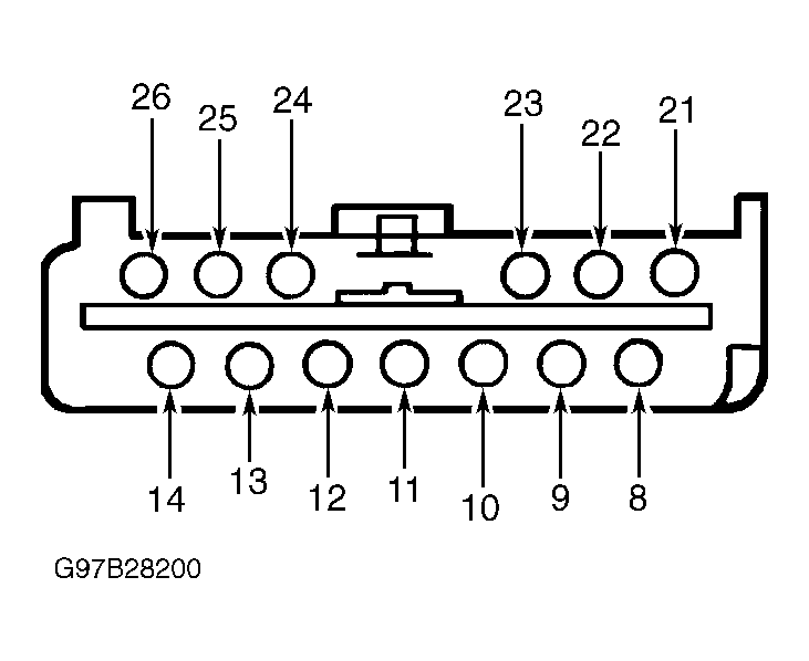
- Disconnect keyless entry control module 13-pin connector C254. Measure voltage between ground and keyless entry control module 13-pin connector C254 terminal No. 14 (Black/White wire) and terminal No. 25 (Black/White wire). See Fig 3
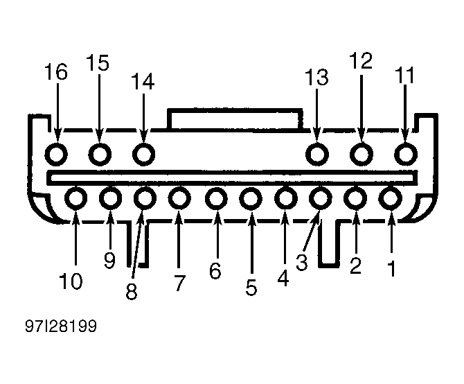
. Measure voltage between ground and keyless entry control module 16-pin connector C235 terminal No. 1 (Red/White wire), 13-pin connector C254 terminal No. 10 (Red/White wire) and terminal No. 23 (Red/White wire). See Fig 2
and Fig 3
. If voltages are 10 or more volts, go to next step. If voltages are less than 10 volts, repair open or short in Black/White or Red/White wire(s).
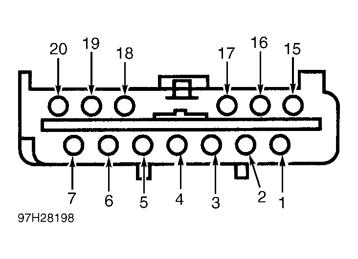
- Disconnect keyless entry control module 13-pin connector C245 and 16-pin connector C235. Check for continuity between ground and keyless entry control module 13-pin connector C245 terminal No. 1 and terminal No. 15. See Fig 1
. Check for continuity between ground and keyless entry control module 16-pin connector C235 terminal No. 5. See Fig 2
. If continuity is present, go to next step. If there is no continuity, repair open in Black or Black/White wire(s), then retest system.
- Reconnect all keyless entry control module connectors. Activate lock and unlock switches. Check continuity of circuit breaker "K" in power distribution box. If continuity is present, go to next step. If continuity is not present, repair short to ground in Red/Orange, Pink/Orange or Pink/Black wire(s); or repair shorted door lock actuator. Retest system.
- Ensure all doors are locked. Disconnect 13-pin connector C245 connect a jumper wire between ground and terminals No. 2 and 16. See Fig 1
. With jumper wires, connect 13-pin connector C254 terminals No. 14 and 25 to 13-pin connector C245 terminals No. 6 and 18. See Fig 1
and Fig 3
. Passenger doors should unlock. Connect another jumper wire between 13-pin connector C254 terminal No. 14 and 13-pin connector C245 terminal No. 3. Driver's door should unlock. If door locks operate as specified, go to next step. If passenger doors unlock, repair Red/Orange or Pink/Black wire(s). Repair driver's door lock motor if necessary. If driver door unlocks, repair Pink/Black or Pink/Orange wire(s). Repair passenger's door lock motor if necessary. Retest system.
- Using an ohmmeter, check for stuck door lock switch. If door lock switch is okay, go to next step. If door lock switch is sticking in LOCK or UNLOCK positions, replace door lock switch, then retest system.
- Disconnect keyless entry control module 13-pin connector C245. Check for continuity between 13-pin connector C245 terminals No. 4 and 5. See Fig 1
. If there is no continuity, go to next step. If continuity is present, repair short between Pink/Yellow and Pink/Light Green wires, then retest system.
- Disconnect keyless entry control module 13-pin connector C245. Check for continuity between ground and keyless entry control module 13-pin connector C245 terminal No. 4. Check for continuity between ground and keyless entry control module 13-pin connector C245 terminal No. 5. See Fig 1
. If there is no continuity, replace keyless entry control module and go to next step. If there is no continuity, repair short to ground in Pink/Yellow or Pink/Light Green wire(s), then retest system.
- Cycle locks several times. If linkage or latches do not bind, go to next step. If linkage or latches bind, lubricate as necessary.
- Remove door trim panel for access to suspect door lock motor. Measure voltage between ground and suspect door lock motor connector while pressing door lock switch to LOCK position. If voltage is less than 10 volts, go to next step. If voltage is 10 volts or more, go to step 13).
- Reconnect keyless entry control module connectors. While pressing lock button, measure voltage between ground and keyless entry control module 13-pin connector C245 terminals No. 2 and 16. See Fig 1
. While pressing unlock button, measure voltage between ground and keyless entry control module 13-pin connector C245 terminals No. 6 and 18. If voltages are 10 volts or more, repair open or short in suspect circuit(s). See WIRING DIAGRAMS
. If voltages are less than 10 volts when switches are pressed, or more than 10 volts with no switches pressed, replace keyless entry control module.
- Measure voltage between ground and suspect door lock motor connector while pressing door lock switch to UNLOCK position. If voltage is 10 volts or more, replace door lock motor. If voltage is less than 10 volts, repair open or short in suspect circuit(s), then go to next step. See WIRING DIAGRAMS
.
- Turn ignition switch to OFF position. Disconnect keyless entry control module 13-pin connector C245. Remove door trim panel for access to suspect door lock switch. Measure resistance in Pink/Yellow wire between suspect door lock switch and keyless entry control module 13-pin connector C245 terminal No. 4. Measure resistance in Pink/Light Green wire between suspect door lock switch and keyless entry control module 13-pin connector C245 terminal No. 5. Measure resistance between ground and Black wire terminal at suspect door lock switch. If resistance is 5 ohms or less, replace suspect door lock switch, then retest system. If resistance is greater than 5 ohms, repair open in suspect circuit(s), then go to next step.
- Turn ignition switch to OFF position. Disconnect keyless entry control module 13-pin connector C245. Measure resistance between ground and Black wire at suspect door lock switch. If door will not lock, measure resistance between ground and keyless entry control module 13-pin connector C245 terminal No. 4 while pressing door lock switch to LOCK position. If door will not unlock, measure resistance between ground and keyless entry control module 13-pin connector C245 terminal No. 5 while pressing door lock switch to UNLOCK position. If resistances are 5 ohms or less, go to next step. If resistance in Black wire is greater than 5 ohms, repair open in Black wire. If resistance readings at keyless entry control module 13-pin connector C245 terminals No. 4 and 5 are greater than 5 ohms, go to step 18).
- Reconnect all keyless entry control module connectors. Measure voltage between ground and keyless entry control module 13-pin connector C245 terminals No. 2 and 16 while pressing door lock switch to LOCK position. Measure voltage between ground and keyless entry control module 13-pin connector C245 terminals No. 6 and 18 while pressing door lock switch to UNLOCK position. If voltages are 10 volts or greater, repair open or short in suspect circuit(s). For reference, see WIRING DIAGRAMS
. If voltages are less than 10 volts, replace keyless entry control module. Retest system.
- Measure resistance between ground and Pink/Yellow wire at suspect door lock switch while pressing door lock switch to LOCK position. Measure resistance between ground and Pink/Light Green wire at suspect door lock switch while pressing door lock switch to UNLOCK position. If resistances are 5 ohms or less, repair open in Pink/Yellow or Pink/Light Green wire. If resistances are greater than 5 ohms, replace suspect door lock switch, then go to next step.
- Turn ignition switch to OFF position. Disconnect keyless entry control module 13-pin connector C245 and 16-pin connector C235. Measure resistance between ground and keyless entry control module 13-pin connector C245 terminals No. 1 and 15. See Fig 1
. Measure resistance between ground and keyless entry control module 16-pin connector C235 terminal No. 5. See Fig 2
. If resistances are 5 ohms or less, check and service loose connections, then retest system. If resistances are greater than 5 ohms, repair Black or Black/White wire(s), and go to next step.
- If door locks do not operate in freezing weather, lubricate door lock and linkage. If door locks operate, go to next step. If door locks still do not operate, go to KEYLESS ENTRY SYMPTOM TO TEST TABLE
.
- Ensure battery is fully charged. Check for binding locks or latches. Check for loose or corroded connections. If door locks still do not operate, go to next step. If door locks operate, system is operating properly at this time.
- Disconnect negative battery cable. Measure resistance in Pink/Yellow wire between keyless entry control module 13-pin connector C245 terminal No. 4 and suspect door lock switch. Measure resistance in Pink/Light Green wire between keyless entry control module 13-pin connector C245 terminal No. 5 and suspect door lock switch. If resistances are 5 ohms or less, go to next step. If resistances are greater than 5 ohms, repair open Pink/Yellow or Pink/Light Green wire(s).
- Measure resistance between ground and Black wire(s) at suspect door lock switch. If resistance is 5 ohms or less, check suspect door lock switch for open. Replace as necessary and go to next step. If resistance is greater than 5 ohms, repair open in Black wire(s).
- Disconnect negative battery cable. Measure resistance between ground and keyless entry control module 13-pin connector C245 terminal No. 4. Measure resistance between ground and keyless entry control module 13-pin connector C245 terminal No. 5. If resistances are greater than 5 ohms, go to next step. If resistances are less than 5 ohms, repair short to ground in Pink/Yellow or Pink/Light Green wire(s).
- Check driver and passenger door lock switches for internal short to ground, and replace as necessary. If door switches are okay, go to next step.
- Measure resistance in Pink/Black wires between keyless entry control module 13-pin connector C245 terminals No. 2 and 16, and each door lock motor. Measure resistance in Pink/Orange wires between keyless entry control module 13-pin connector C245 terminals No. 6 and 18, and each door lock motor. If resistance is 5 ohms or less, go to next step. If resistance is greater than 5 ohms, repair open in Pink/Black or Pink/Orange wire.
- Measure resistance between ground and Pink/Orange wire at anti-theft alarm control module. Measure resistance between ground and Red/Orange wire at anti-theft alarm control module. Measure resistance between ground and Pink/Black wire at anti-theft alarm control module. If resistances are greater than 5 ohms, replace keyless entry control module. If resistances are 5 ohms or less, repair short to ground in suspect circuit(s).
 Courtesy of FORD MOTOR CO.
 Courtesy of FORD MOTOR CO.
 Courtesy of FORD MOTOR CO.