Test D: Single Window Inoperative
- Determine which window is inoperative. If left door window is inoperative, go to next step. If right door window is inoperative, go to step 6).
- To check left window power supply, remove master window switch. See MASTER WINDOW CONTROL SWITCH & RIGHT WINDOW CONTROL SWITCH under REMOVAL & INSTALLATION. Connect a voltmeter between ground and circuits as indicated in MASTER WINDOW SWITCH table. See Fig 2
. Actuate master switch in appropriate direction and observe reading. If battery voltage is present, go to next step. If battery voltage is absent, replace master window regulator switch and retest system.
MASTER WINDOW SWITCH
| Pin No. (Wire Color) |
Switch Position |
| 3 (WHT/YEL) |
Right Window Down |
| 7 (TAN/LT BLU) |
Right Window Up |
| 10 (WHT/BLK) |
Left Window Up |
| 14 (YEL) |
Left Window Down |
- To check inoperative window motor circuits, gain access to inoperative window motor connector. See WINDOW MOTOR
under REMOVAL & INSTALLATION. Disconnect motor connector. Connect voltmeter between ground and circuits as indicated in MASTER WINDOW SWITCH table. Actuate master switch in appropriate direction and observe reading. If battery voltage is present, go to step 5). If battery voltage is absent, go to next step.
- To check circuit continuity, disconnect left power window switch. Measure resistance of suspect circuit between harness connector and left door master window switch. If resistance is 5 ohms or less, go to next step. If resistance is more than 5 ohms, repair open circuit and retest system.
- To check power window motor, with a jumper, connect battery voltage to pin No. 1 at power window motor. With a second jumper, connect one end to ground and momentarily connect other end to pin No. 2 of window motor. To reverse motor direction, switch jumper leads at window motor. If power window motor operates correctly, motor is okay. Restore vehicle and retest system. If motor does not operate correctly, replace window motor and retest system. See WINDOW MOTOR
under REMOVAL & INSTALLATION.
- To check inoperative right door window, remove right door window switch. See appropriate WINDOW SWITCH
under REMOVAL & INSTALLATION. Using a voltmeter, connect from ground to right window control switch connector, pin No. 2 (White/Yellow wire). See Fig 1
. Actuate right window at left door master window control switch in down position and observe reading. Move voltmeter probe from pin No. 2 to pin No. 4 (Tan/Light Blue wire). Actuate right window control switch in up position and observe reading. If battery voltage is observed in either direction, go to next step. If battery voltage was not observed, replace master window control switch and retest system.
- To check power supply to right window switch, connect voltmeter from ground to right window switch connector, pin No. 3 (Pink wire). If voltage is 10 volts or more, go to next step. If voltage is less than 10 volts, repair open in Pink wire and retest system.
- To check right door window motor down circuit, measure voltage between ground and switch connector, pin No. 1 (Yellow/Red wire) while actuating control switch in down position. If battery voltage is present go to next step. If battery voltage is not present, replace right door window control switch and retest system. See procedures in WINDOW SWITCH
under REMOVAL & INSTALLATION.
- To check right door window motor up circuit, move voltmeter probe from switch connector, pin No. 1 (Yellow/Red wire) to switch connector, pin No. 5 (Red/Yellow wire). See Fig 1
. Actuate window switch in up position. If battery voltage is present, go to next step. If battery voltage is absent, replace right door window control switch and retest system. See WINDOW SWITCH
under REMOVAL & INSTALLATION.
- To check right door window down power supply, disconnect voltmeter and power window motor connector. Connect voltmeter from ground to window switch, pin No. 1 (Yellow/Red wire). Actuate window switch in down position. If battery voltage is present, go to next step. If battery voltage is absent, repair open in Yellow/Red wire and retest system. See Fig 1
.
- Move voltmeter probe from switch connector pin No. 1 to switch connector pin No. 5 (Red/Yellow wire). See Fig 1
. Actuate window switch in up position. If battery voltage is present, return to step 5). If battery voltage is absent, repair open in Red/Yellow wire and retest system.
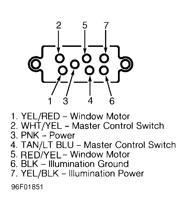 Courtesy of FORD MOTOR CO.
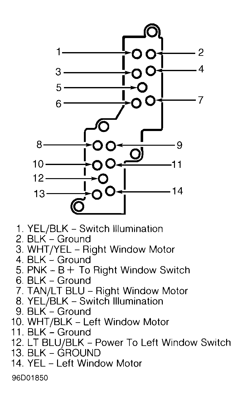 Courtesy of FORD MOTOR CO.