Code 2 - Open Isolation Valve Circuit
- Turn ignition off. Disconnect negative battery cable. Disconnect control module connector. See COMPONENT LOCATIONS
. Gently pull on terminal No. 13 (Pink/Light Green wire) of control module and control module harness connector. See Figure
. If connector terminal is fully engaged and corresponding terminal of control module is okay, leave control module disconnected and go to next step. If terminal is loose or has pulled out of connector, repair or replace terminal or connector as necessary and go to step 6). If control module terminal is loose, bent, deformed, corroded or missing, replace control module and go to step 6).
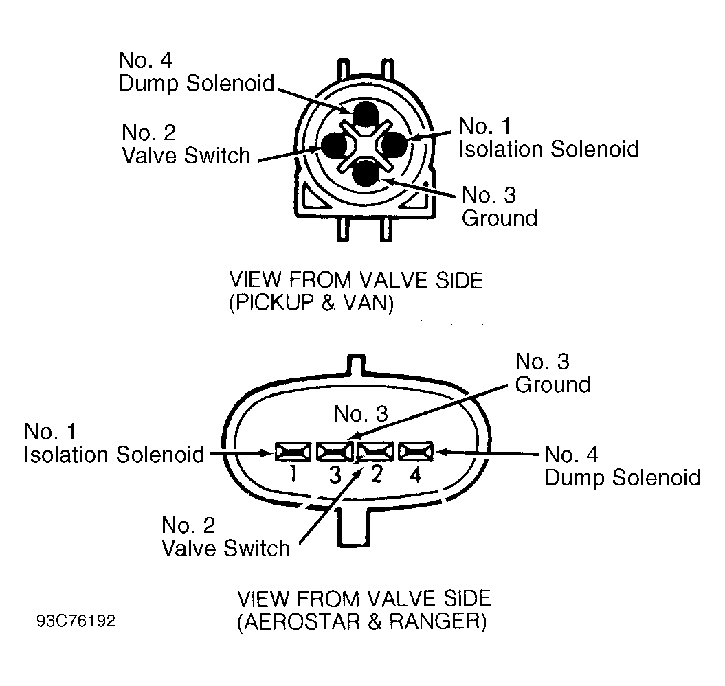
- Disconnect and inspect 4-pin valve assembly connector. Valve assembly is located on left frame rail, toward rear of engine compartment. Gently pull on terminal No. 1 (Pink/Light Green wire) of valve assembly connector and valve assembly harness connector. See Fig 1
. If terminal is fully engaged in connector, leave valve assembly disconnected and go to next step. If terminal is loose or has pulled out of connector, repair or replace terminal or connector as necessary and go to step 6). If valve assembly terminal is loose, bent, deformed, corroded or missing, replace valve assembly and go to step 6).
- Using an ohmmeter, measure resistance between terminal No. 13 (Pink/Light Green wire) of control module harness connector and terminal No. 1 (Pink/Light Green wire) of valve assembly harness connector. If resistance is less than 10 ohms, go to next step. If resistance is more than 10 ohms, repair open in Pink/Light Green wire and go to step 6).
- Using an ohmmeter, measure resistance between terminal No. 1 (ISO) and terminal No. 3 (ground) of 4-pin valve assembly connector. See Fig 1
. If resistance is 6 ohms or less, go to next step . If resistance is more than 6 ohms, replace valve assembly. Go to step 6).
- Ensure all preceding diagnostic steps have been completed and involved wiring integrity has been verified. If steps have not been completed, return to last diagnostic step completed. If all diagnostic steps have been completed, replace control module and go to next step. If control module has already been replaced with no resolution of problem, replace valve assembly and go to next step.
- Ensure ignition is off. Reconnect negative battery cable. Ensure all connectors are connected and secure. Retrieve trouble codes. See RETRIEVING TROUBLE CODES
. If Code 16 is present, go to CODE 16 under TEST DRIVE
. If Code 2 is present, go to next step. If any other trouble code is present, go to corresponding test for appropriate trouble code.
- Ensure all preceding diagnostic steps have been completed and involved wiring integrity has been verified. If steps have not been completed, return to last diagnostic step completed. If all diagnostic steps have been completed, go to next step.
- If previous diagnostic steps have been completed, problem is most likely wiring related. Go to INTERMITTENT DIAGNOSIS
and perform tests on all involved circuits. If problem is not resolved, go to step 5). If problem is resolved, repair is complete. Go to CODE 16 under TEST DRIVE
.
 Courtesy of FORD MOTOR CO.