- Remove torque converter. Mount transaxle in a appropriate holding fixture. Place in vertical position and drain fluid.
- Place in horizontal position. Remove 2 (8 mm) speedometer cover bolts, cover and seal. Discard seal. Lift speedometer drive gear assembly and bearing from case. Bearing sits on top of speedometer drive gear.
- Remove 3 (8 mm) bolts from overdrive servo cover. Servo cover is under pressure and must be retained when removing bolts. Mark and remove cover, piston assembly and spring. Discard "O" ring from cover. Remove 3 low-intermediate servo cover bolts. Mark and remove cover, piston assembly and spring. Remove and discard gasket.
- Install Step Plate Adapter (D80L-630-3) into right-hand output shaft opening; hold adapter in position with grease. Screw output shaft Seal Remover (T74P-6700-A) into metal seal and protector. Tighten screw on end of seal remover until metal seal protector is removed. Reinstall remover and repeat procedure to remove seal.
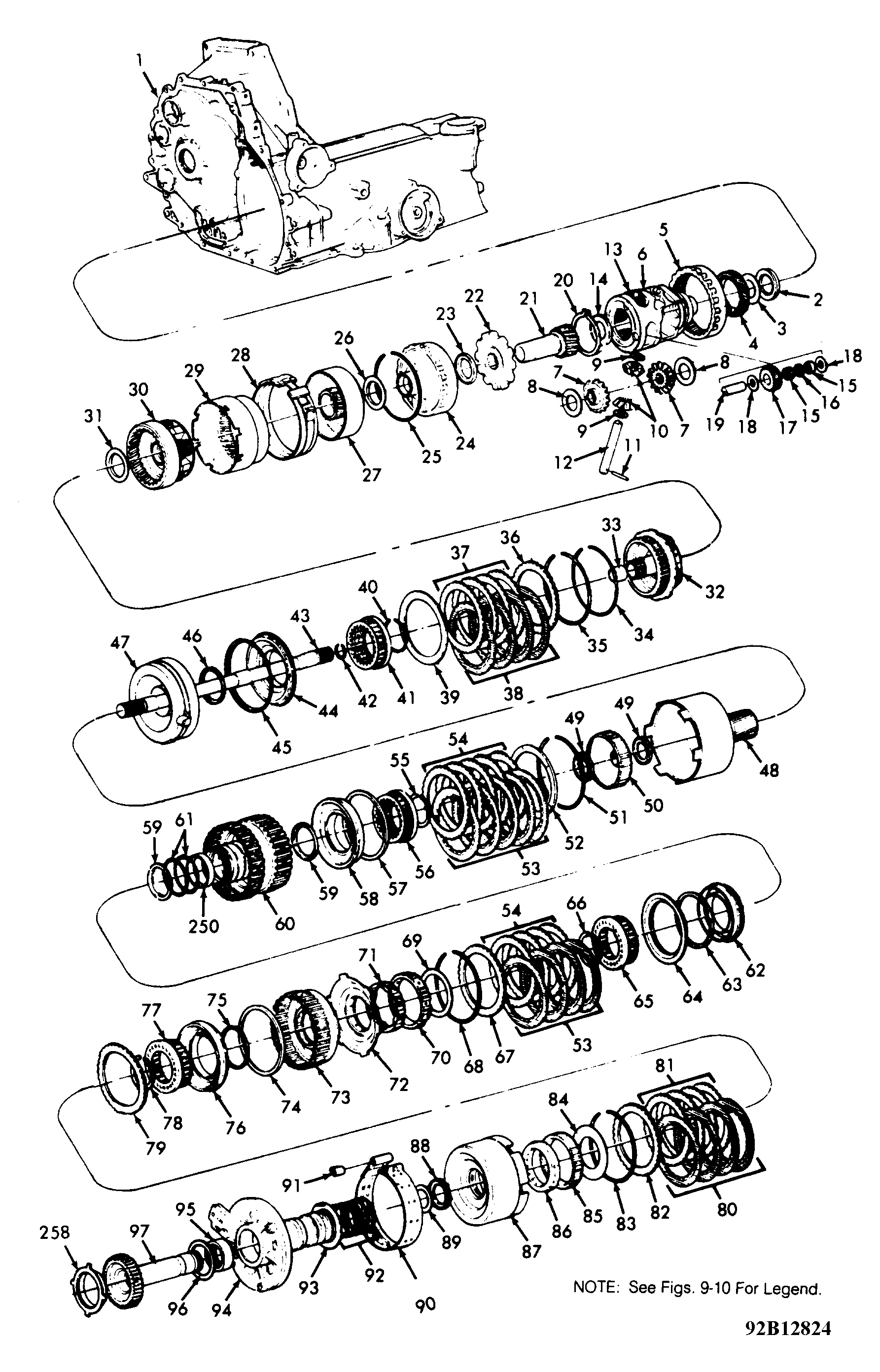 Courtesy of FORD MOTOR CO.
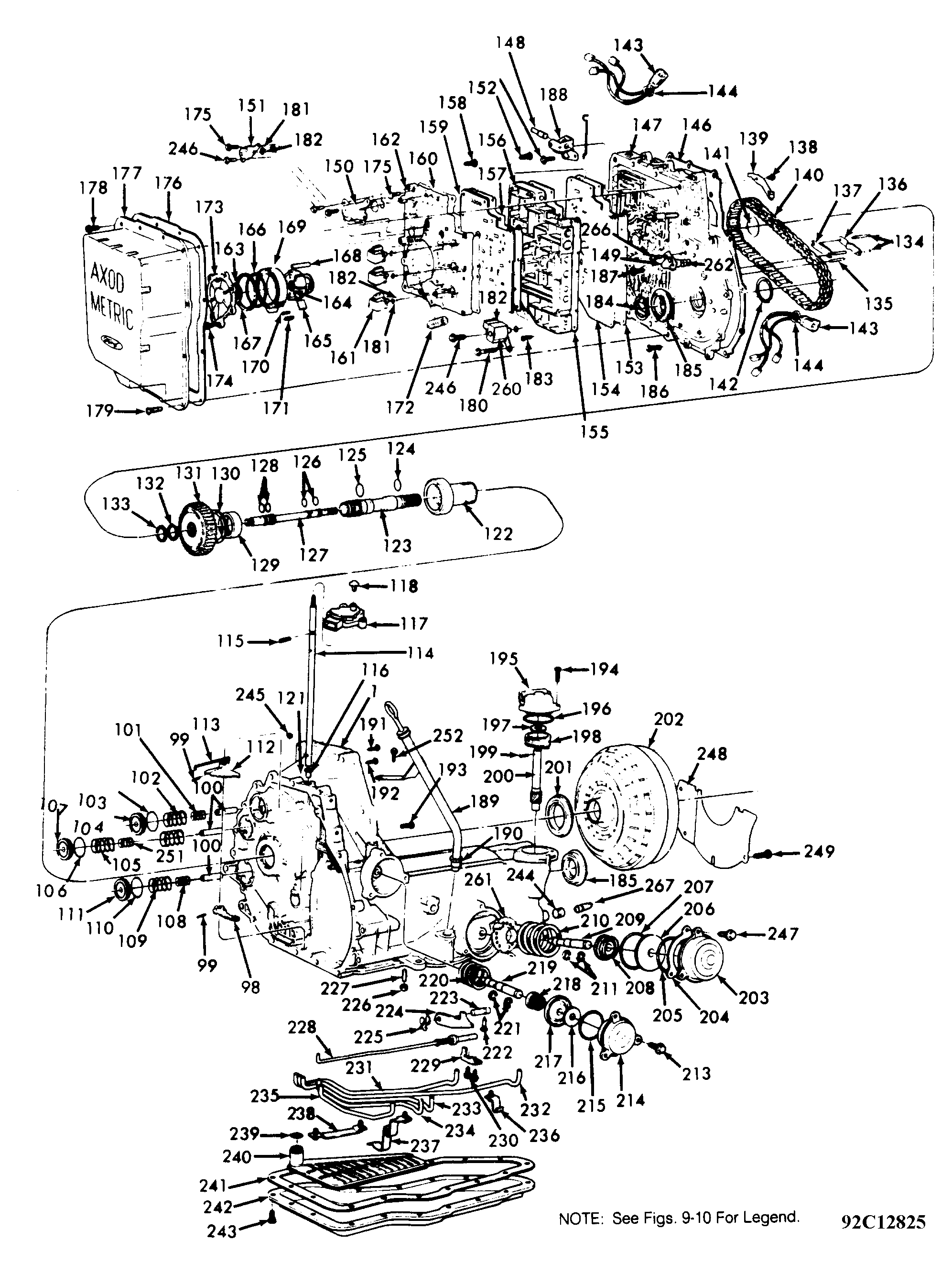 Courtesy of FORD MOTOR CO.
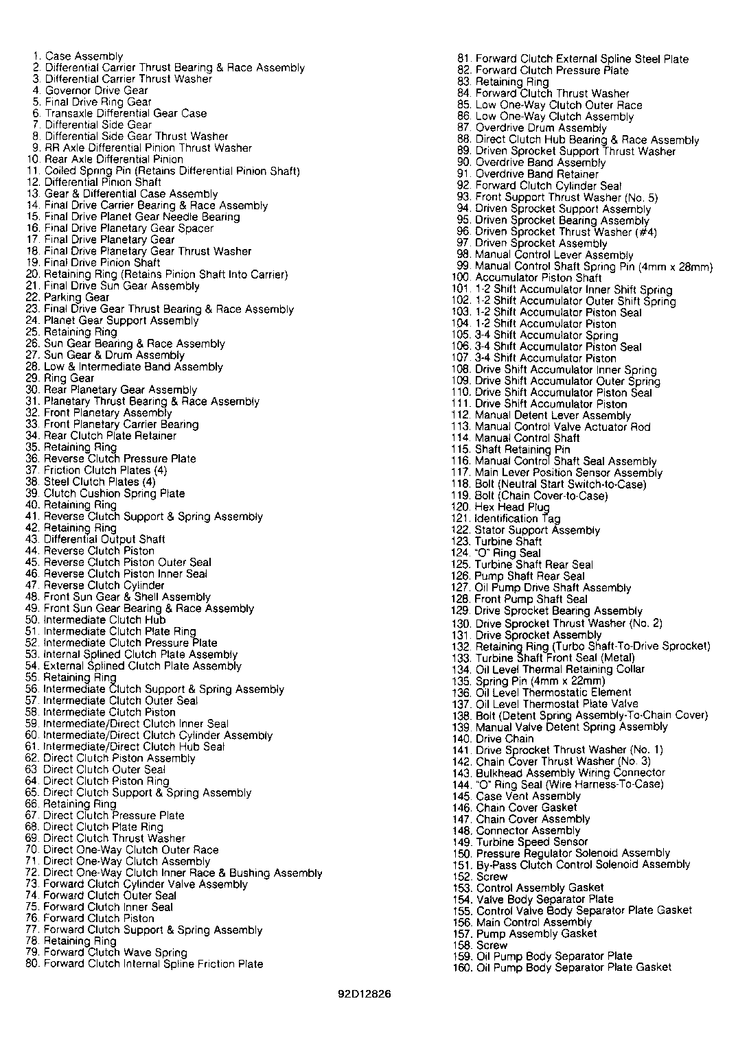 Courtesy of FORD MOTOR CO.
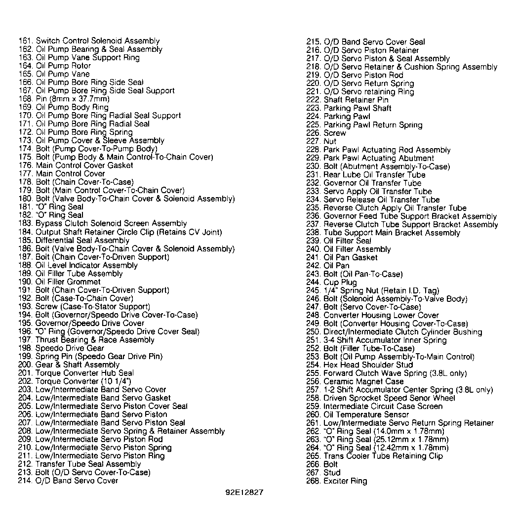 Courtesy of FORD MOTOR CO.
- Remove 2 (8 mm) bolts from Manual Lever Position Sensor (MLPS) and remove sensor. Remove dipstick tube and dipstick from case. Remove 9 chain cover bolts from inside torque converter housing.
- Using a slide hammer and Seal Puller (1175-AC), remove converter oil seal from input shaft. Rotate transaxle to vertical position. Remove 12 valve body cover bolts. Remove cover and discard gasket.
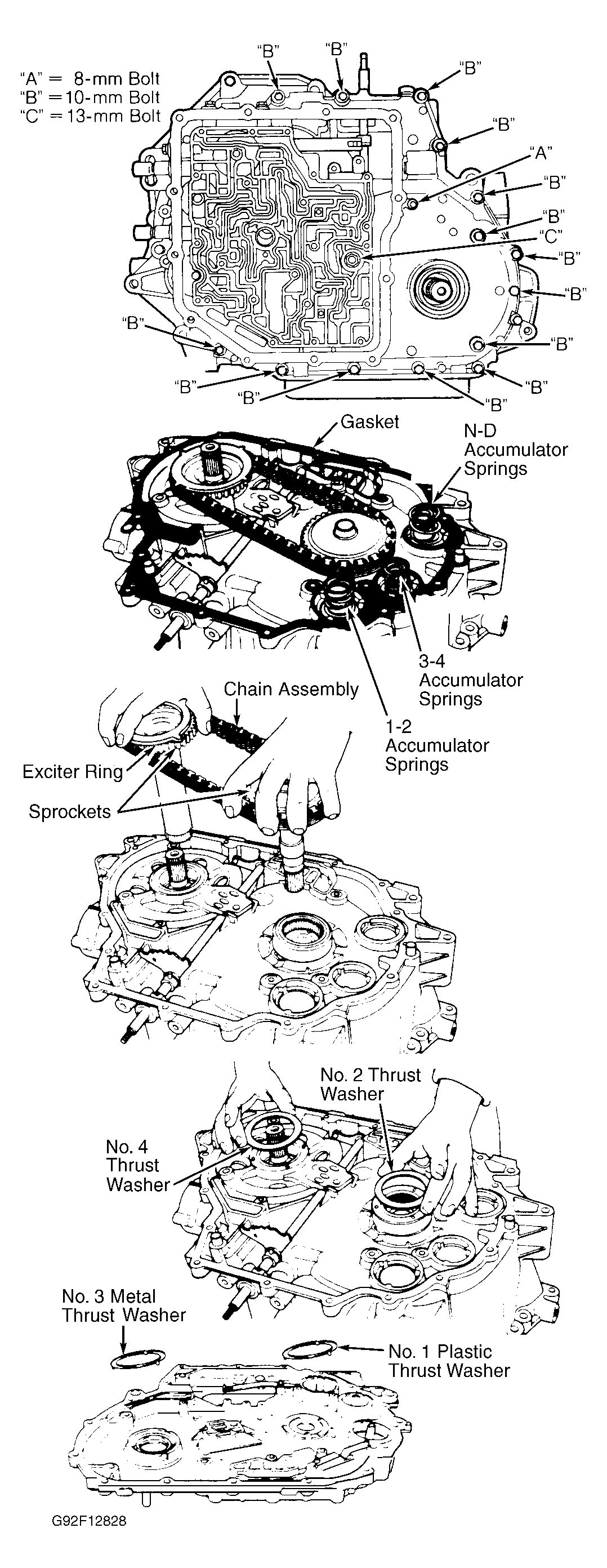
- Disconnect electrical connectors from pressure switches and solenoid. Use both hands. DO NOT pull on wires. Compress tabs on both sides of bulkhead connector from inside of chain cover and remove connector and wiring. See Figure
.
- Using a 9 mm wrench on flats of manual shaft, rotate shaft clockwise to position manual linkage in low detent (manual valve all the way in). Mark and remove 22 oil pump and valve body bolts, noting length and location. See Figure
.
CAUTION:
Do not remove 2 bolts holding oil pump and valve body together. Do not remove 6 oil pump cover bolts.
- Rotate valve body clockwise and remove manual valve link from manual valve. Disconnect manual valve link from detent lever. Remove pump and valve body assembly.
- Pull oil pump drive shaft out of case and remove 4 Teflon seals from shaft. Discard seals.
- Place transaxle in vertical position. Remove and discard left output shaft circlip. Screw Seal Remover (T74P-6700-A) into metal seal protector. Tighten screw of seal remover until metal seal protector is removed. Repeat procedure to remove seal.
- Remove Turbine Speed Sensor (TSS) from chain cover. Mark and remove 16 chain cover bolts. Note length and location of bolts. Chain cover is under spring pressure; remove carefully. See Fig 5
. Note location of accumulator springs and tag to ensure reassembly to original location. Mark and remove No. 1 (plastic) thrust washer from chain cover. Mark and remove No. 3 (metal) thrust washer from chain cover.
NOTE:
Measure chain stretch at mid-point between sprockets before disassembly. If stretch exceeds 7/8", replace chain.
- Simultaneously lift both sprockets out with chain assembly. Remove cast iron sealing ring from input shaft. Mark and remove No. 2 and No. 4 thrust washers from drive and driven sprocket supports. Inspect drive sprocket support bearing to determine if it needs replacing. If bearing is okay, remove 6 Torx (T30) bolts attaching support to case.
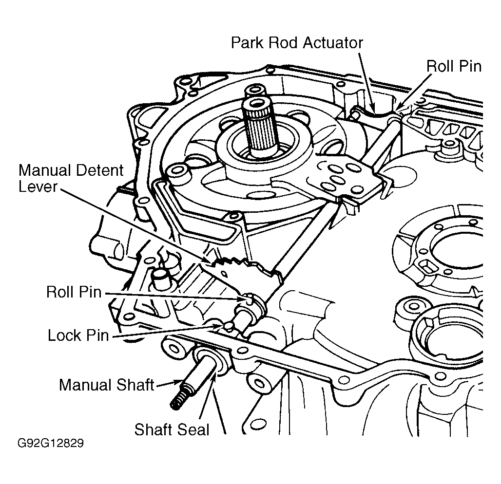
- Using Pin Remover (D81P-3504-N), remove lockpin and 2 roll pins from manual shaft. Be careful not to damage machined surfaces. Slide shaft out and pry seal from case. See Fig 6
.
 Courtesy of FORD MOTOR CO.
 Courtesy of FORD MOTOR CO.
- Using a straightedge, note whether driven sprocket support machined bolt hole surface is above or below the case machined surface. Note for reassembly reference. Remove driven sprocket support assembly.
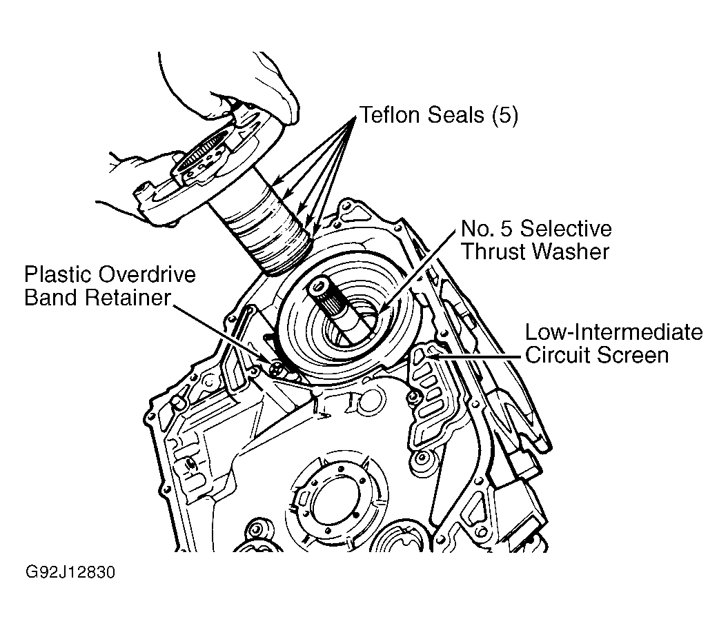
- Remove 5 Teflon seals from support assembly. Mark and remove No. 5 selective thrust washer. Washer may stay on support assembly during removal. Using a wire hook, if necessary, remove No. 8 selective thrust washer and No. 9 needle bearing. Remove plastic overdrive band retainer and overdrive band. See Fig 7
. Remove filter screen. Clean filter with compressed air. Replace filter tube lip seal.
- Position transaxle with oil pan up. Remove 17 oil pan cover bolts. Remove cover and discard gasket. Remove reverse apply tube/oil filter bolt and bracket. Remove oil filter screen and discard lip seal.
 Courtesy of FORD MOTOR CO.
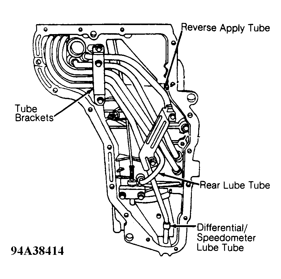
- Remove tube retaining bracket bolts and brackets. If necessary, use Tube Remover (T86P-70001-A) and a slide hammer to remove lube tubes. Tubes are retained with Loctite. See Fig 8
.
 Courtesy of FORD MOTOR CO.
NOTE:
For complete transaxle disassembly, reverse apply tube MUST be removed prior to removing the reverse clutch or differential.
- Remove 2 parking rod abutment bolts. Remove parking rod by lifting to clear abutment and lower from case. Remove parking pawl shaft roll pin. Use magnet to remove parking pawl shaft. Remove parking pawl and return spring. Loosen 19 mm reverse clutch anchor pin nut and remove 6 mm Allen head bolt.
NOTE:
It is necessary to modify Front Clutch Loading Tool (T86P-70389-A) for use on 3.2L transaxle. Remove .02" (.5 mm) of material from hook end of tool.
- Place transaxle in horizontal position. Install Front Clutch Loading Tool (T86P-70389-A). Lift front sun gear and shell assembly out of case. Install hook portion of Front Clutch Loading Tool (T86P-70389-A) on inner diameter of reverse clutch cylinder. Grasp outer diameter with fingertips and slide clutch assembly out of case.
- Rotate transaxle to vertical position. Grasp front planetary shaft and lift out both front and rear planetary assemblies. Lift out low-intermediate drum and sun gear assembly. Remove low-intermediate band.
- Remove final drive assembly snap ring from case using a screwdriver inserted through side of case. Lift out final drive assembly using output shaft. See Fig 9
.
- Remove and discard rear lube tube seal using a 3/8" rod or drift. Remove final drive ring gear from case. Remove No. 18 thrust washer and No. 19 needle bearing. Thrust washer may remain on final drive next to speedometer gear. Tap seal towards inside of case. If case replacement is necessary, remove Torx bolts and converter support from old case at this time.