Coil Primary Circuit Test
- Perform step 1) of CONTROL MODULE FEED TEST for Red wire circuit. If voltage was within 1 volt of battery voltage, turn ignition switch from "RUN" to "OFF". A spark should be seen each time ignition is turned off. Place ignition switch to "RUN" position. If sparks occur, go to CONTROL MODULE & STATOR TEST . If no sparks occur, go to next step.
- Connect positive lead of voltmeter to ignition coil "BAT" terminal and negative lead to ground. Reading should be 5-8 volts. If so, go to step 11). If less than 6 volts, go to step 10).
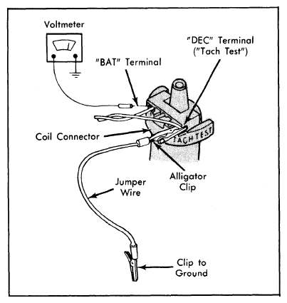 Courtesy of FORD MOTOR CO.
- If voltage in step 2) is battery voltage, disconnect 4-wire connector at control module. Insert a jumper wire (paper clip) into the 4-wire harness connector's terminals that mate with the control module's Green and Black wires (terminals No. 1 and 8).
- Connect voltmeter positive lead to ignition coil "BAT" terminal and negative lead to ground. Measure voltage. If battery voltage exists, go to step 6).
- If voltage now reads 6-8 volts, substitute (but do not install) a known good control module. Repeat previous tests. If sparks occur, reconnect original control module and retest. If no spark now occurs, replace control module.
- If voltage in step 4) was battery voltage, make sure coil connector is fully engaged on primary terminals of ignition coil. Ground the "TACH TEST" terminal of coil. See Fig 1. Connect voltmeter positive lead to coil "BAT" terminal and negative lead to ground.
- If reading is now 6-8 volts, remove ground wire from "TACH TEST" terminal of coil connector. Ground jumper wire (paper clip) in 4-wire connector. Again measure voltage at coil "BAT" terminal. Reading should be approximately 6-8 volts. If so, go to step 9).
- If not, repair wire from control module to coil (mates with Green wire). Remove jumper wire (paper clip) from 4-wire connector. Reconnect control module and retest system. If sparks occur, system is okay.
- If voltage in step 7) was 6-8 volts, repair the Black wire from control module to distributor. Remove jumper wire (paper clip) from 4-wire connector and retest system. If sparks occur, system is okay.
- If voltage in step 2) was less than 6 volts, repair wire feeding the ignition coil "BAT" terminal and retest system. If spark occurs at modified plug, system is okay.
- If voltage in step 2) was 6-8 volts but engine would not run, or if voltage in step 6) was battery voltage, remove paper clip and reconnect control module. Substitute (but do not install) a known good ignition coil and repeat system test. If sparks occur, reconnect original coil and retest. If no sparks occur, replace ignition coil.
- If no sparks occurred with substitute coil, connect original ignition coil and be sure connector is fully engaged over terminals. Substitute (but do not install) a known good control module and repeat tests. If sparks occur, reconnect original module and retest. If no sparks occur, replace control module.