2.0L Engine (Service Information): Removal: Engine
 Courtesy of CHRYSLER GROUP, LLC
- Remove hood.
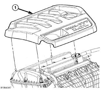
- Remove engine cover (1).
 Courtesy of CHRYSLER GROUP, LLC
- Perform fuel pressure release procedure. Refer to FUEL SYSTEM PRESSURE RELEASE PROCEDURE
.
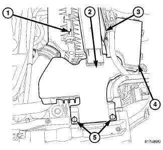
- Remove retainers (5) and remove air inlet (2).
- Remove air cleaner housing assembly (1) and clean air hose. Refer to BODY, AIR CLEANER, REMOVAL .
 Courtesy of CHRYSLER GROUP, LLC
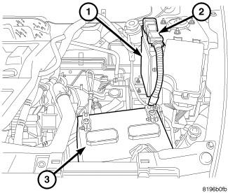
- Disconnect both cables from battery (3).
- Remove battery (3).
 Courtesy of CHRYSLER GROUP, LLC
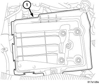
- Remove battery tray (1).
- Drain cooling system. Refer to STANDARD PROCEDURE
.
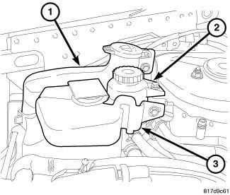 Courtesy of CHRYSLER GROUP, LLC
- Remove coolant reservoir (3).
- Remove power steering reservoir (2).
- Remove windshield washer reservoir (1).
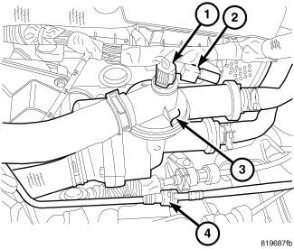 Courtesy of CHRYSLER GROUP, LLC
- Remove coolant hoses from coolant adapter (3).
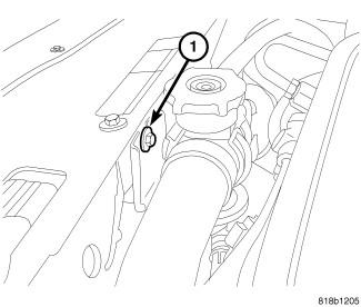 Courtesy of CHRYSLER GROUP, LLC
- Remove grill closure panel.
- Remove upper radiator hose support (1).
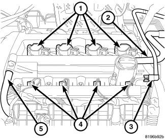 Courtesy of CHRYSLER GROUP, LLC
- Disconnect engine electrical connectors and reposition harness.
- Remove air intake tube from throttle body.
- Disconnect fuel line (3) from fuel rail.
 Courtesy of CHRYSLER GROUP, LLC
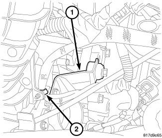
- Remove vacuum lines from throttle body and intake manifold.
- Remove harness from intake (2).
- Remove throttle body support bracket (1).
Courtesy of CHRYSLER GROUP, LLC
- Disconnect electronic throttle control and manifold flow control valve electrical connectors.
- Remove PCV hose (5), and make-up air hose (2) from valve cover.
- Remove dipstick.
 Courtesy of CHRYSLER GROUP, LLC
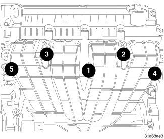
- Remove intake bolts (1 - 5) and remove intake.
- Disconnect electrical connectors and reposition harness.
- Remove accessory drive belt.
 Courtesy of CHRYSLER GROUP, LLC
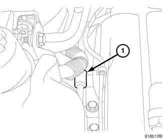
- Remove power steering line support at engine mount (1) and exhaust manifold.
- Remove power steering pump and set aside.
- Remove upper idler pulley.
 Courtesy of CHRYSLER GROUP, LLC
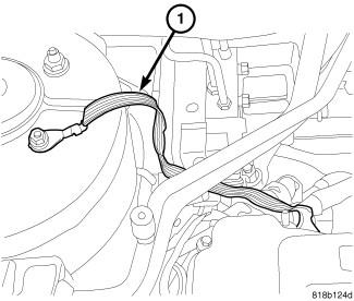
- Remove ground strap near right tower.
- Raise vehicle.
- Remove right front tire.
- Remove splash shield.
 Courtesy of CHRYSLER GROUP, LLC
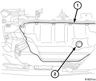
- Drain oil (2).
 Courtesy of CHRYSLER GROUP, LLC
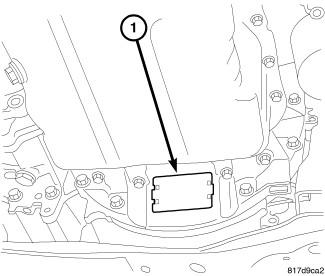
- Remove inspection cover (1) and mark torque converter to flywheel.
 Courtesy of CHRYSLER GROUP, LLC
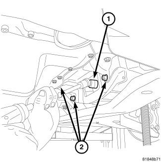
- Remove torque converter bolts (1).
- Remove lower bellhousing bolts (2).
 Courtesy of CHRYSLER GROUP, LLC
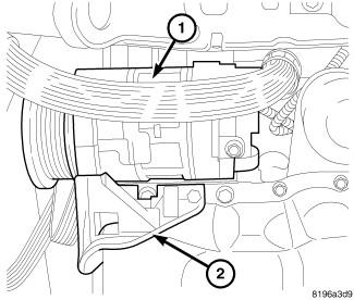
- Remove A/C compressor (1) mounting bolts.
- Remove generator and lower idler pulley.
 Courtesy of CHRYSLER GROUP, LLC
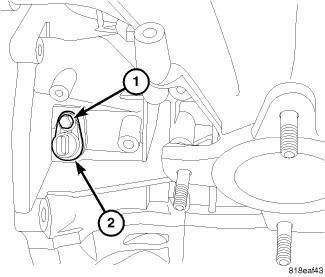
- Disconnect crankshaft position sensor electrical connector and remove crankshaft position sensor (2).
 Courtesy of CHRYSLER GROUP, LLC
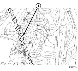
- Remove exhaust variable valve timing solenoid.
- Install engine lift chain (1) as shown in illustration to cylinder head.
- Connect the chain to the rear engine lift hook.
- Install engine lifting crane.
 Courtesy of CHRYSLER GROUP, LLC
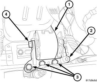
- Remove right engine mount through bolt (4).
- Remove engine mount adapter retaining bolts (3) and mount adapter (2).
- Lift engine from engine compartment.