2.0L Engine (Service Information): Installation: Engine
 Courtesy of CHRYSLER GROUP, LLC
- Position engine assembly over vehicle and slowly lower the engine into place.
- Continue lowering engine until engine and transaxle are aligned. to mounting locations.
- Install engine mount adapter (2) and tighten bolts (3). Install mount through bolt (4) and tighten to 118 N.m (87 ft. lbs.).
 Courtesy of CHRYSLER GROUP, LLC
- Remove engine lift chain (1).
- Install oil control valve.
 Courtesy of CHRYSLER GROUP, LLC
- Raise vehicle.
- Install A/C compressor (1).
 Courtesy of CHRYSLER GROUP, LLC
- Install exhaust manifold and heat shields (2). Refer to MANIFOLD, EXHAUST, INSTALLATION .
- Install oxygen sensor and connect electrical connector (3).
 Courtesy of CHRYSLER GROUP, LLC
- Install crankshaft position sensor (2) and connect connector.
Courtesy of CHRYSLER GROUP, LLC
- Install manifold to exhaust pipe bolts (1) and tighten bolts.
- Install generator.
 Courtesy of CHRYSLER GROUP, LLC
- Install lower bell housing bolts (2) and tighten bolts.
- Align torque converter and flex plate mark. Install torque converter bolts (1) and tighten.
 Courtesy of CHRYSLER GROUP, LLC
- Install inspection cover (1).
 Courtesy of CHRYSLER GROUP, LLC
- Install crankshaft damper
- Install Damper holder (special tool #9707, Holder, Vibration Damper) (1).
- Apply clean engine oil crankshaft damper bolt threads and between bolt head and washer. Tighten bolt to 210 N.m (155 ft. lbs.).
- Install right splash shield.
- Install tire.
 Courtesy of CHRYSLER GROUP, LLC
- Install coolant hose to oil cooler (2).
- Install new oil filter (3).
- Lower vehicle.
- Install upper idler pulley.
 Courtesy of CHRYSLER GROUP, LLC
- Install coolant adapter assembly (3).
 Courtesy of CHRYSLER GROUP, LLC
- Install Ground strap (1) near right strut tower.
 Courtesy of CHRYSLER GROUP, LLC
- Install power steering line support bracket (1).
- Install power steering pump.
- Install accessory drive belt.
- Connect electrical connectors at block ground, starter, A/C compressor, knock sensor, Oil pressure sensor, generator, Coolant temperature sensor at block, and block heater (if equipped).
 Courtesy of CHRYSLER GROUP, LLC
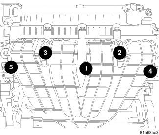
- Install intake manifold. Refer to MANIFOLD, INTAKE, INSTALLATION .
 Courtesy of CHRYSLER GROUP, LLC
- Install throttle body support bracket (1).
- Install harness retainer (2).
- Install engine oil level indicator.
 Courtesy of CHRYSLER GROUP, LLC
- Install PCV hose (5) to valve cover.
- Install make-up air hose (2).
- Connect manifold flow control valve and electronic throttle control electrical connectors.
- Install vacuum lines at throttle body and intake manifold.
- Install intake air tube to throttle body.
Courtesy of CHRYSLER GROUP, LLC
- Connect coil electrical connectors (1).
- Connect injector electrical connectors (4).
- Connect fuel line (3) to rail.
- Connect intake and exhaust oil control valve electrical connectors.
 Courtesy of CHRYSLER GROUP, LLC
- Install grill trim panel.
- Install upper radiator support bracket (1).
Courtesy of CHRYSLER GROUP, LLC
- Connect coolant temperature sensor (1).
- Connect capacitor electrical connector (2).
- Install coolant hoses at coolant adapter (3).
 Courtesy of CHRYSLER GROUP, LLC
- Install coolant reservoir (3) and connect hose.
 Courtesy of CHRYSLER GROUP, LLC
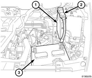
- Install battery tray (1).
 Courtesy of CHRYSLER GROUP, LLC
- Install battery (3).
- Connect battery cables.
 Courtesy of CHRYSLER GROUP, LLC
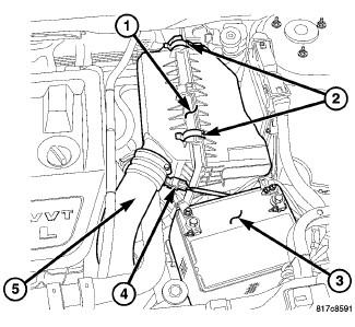
- Install air cleaner housing (1) and connect inlet air hose.
- Install clean air hose (5).
- Fill with coolant.
- Fill with oil.
- Start engine and check for leaks.
 Courtesy of CHRYSLER GROUP, LLC
- Install engine cover (1).
- Install hood.