Left Side Knock Sensor
- Remove the mixing chamber. Refer to MANIFOLD, INTAKE, REMOVAL
.
 Courtesy of CHRYSLER GROUP, LLC
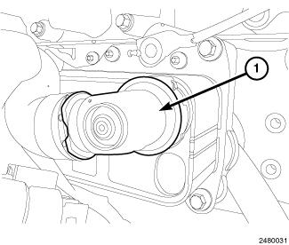
- Remove the serpentine belt.
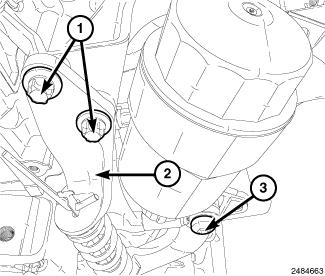
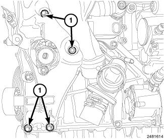
- Install the accessory drive belt tensioner.
- Tighten bolts (1) to 20 N.m (177 in. lbs.).
- Tighten bolt (3) to 45 N.m (33 ft. lbs.).
 Courtesy of CHRYSLER GROUP, LLC
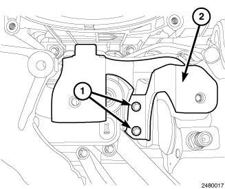
- Remove bolts (1) and the intake manifold support bracket (2).
 Courtesy of CHRYSLER GROUP, LLC
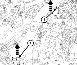
- Release the lock tabs (1) and lift up on the wire harness.
 Courtesy of CHRYSLER GROUP, LLC
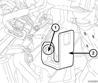
- Remove bolt (1) and wire harness support bracket (2).
 Courtesy of CHRYSLER GROUP, LLC
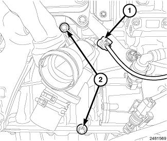
- Disconnect the coolant temp sensor (1) harness connector.
- Remove the three cooling manifold bolts (2).
 Courtesy of CHRYSLER GROUP, LLC
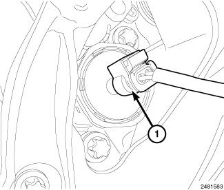
- Disconnect the oil jet control valve (1) harness connector.
 Courtesy of CHRYSLER GROUP, LLC
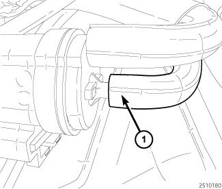
- Disconnect the coolant pump actuator vacuum line (1).
 Courtesy of CHRYSLER GROUP, LLC
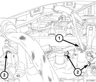
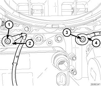
- Disconnect the coolant temperature sensor (1) harness connector.
- Remove the two bolt (2) from thermostat housing.
 Courtesy of CHRYSLER GROUP, LLC
- Remove the bolts (1) from the cooling manifold.
 Courtesy of CHRYSLER GROUP, LLC
- Disconnect the coolant hose (1) to the oil cooler and remove cooling manifold.
 Courtesy of CHRYSLER GROUP, LLC
- Remove bolt (1) and the left knock sensor (2).