Ignition System Circuit (3.0L)
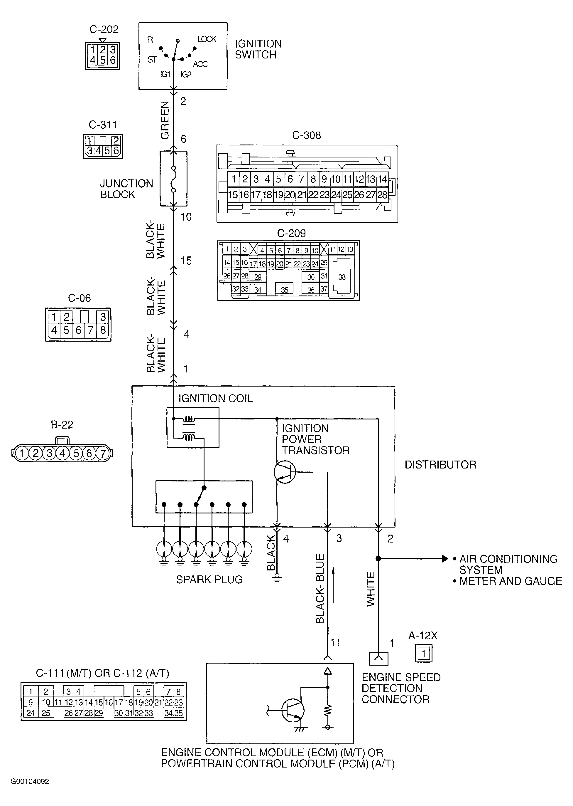 Courtesy of CHRYSLER CORP.
- Check distributor connector B-22 for loose, damaged or corroded terminals. If connection is okay, go to next step. If faulty connections are found, repair connector. After repairs, recheck system operation.
- Test ignition coil. See IGNITION COIL
under OPTICAL IGNITION SYSTEM (3.0L). Replace as necessary. If ignition coil is okay, go to next step.
- Check ignition power transistor. See IGNITION COIL POWER TRANSISTOR
- Disconnect distributor connector B-22. Turn ignition on. Using DVOM, measure voltage between ground and distributor connector B-22 terminal No. 1 (Black/White wire). Turn ignition off. If battery voltage is indicated, go to next step. If battery voltage is not indicated, repair open in Black/White wire or Green wire between distributor connector B-22 and ignition switch connector C-202 terminal No. 2. Circuit includes intermediate connectors C-06, C-209, C-308 and C-311. See Fig 1
.
- Using DVOM, measure resistance between ground and distributor connector B-22 terminal No. 4 (Black wire). If resistance is less than 2 ohms, go to next step. If resistance is 2 ohms or more, repair open or poor connection on Black wire to ground.
- Check ECM connector C-111 (M/T) or PCM connector C-112 (A/T) for loose, damaged or corroded terminals. If faulty connections are found, repair connector. After repairs, recheck system operation. If connections are okay, go to next step.
- Check for open, short to ground or damage to Black/Blue wire between distributor connector B-22 terminal No. 3, and ECM connector C-111 terminal No. 11 or PCM connector C-112 terminal No. 11. If circuit is okay, go to next step. Repair faulty circuits as necessary. After repairs, recheck operation.
- Check for open, short to ground or damage to White wire between engine speed detection connector A-12X terminal No. 1, and distributor connector B-22 terminal No. 2. Repair faulty circuit as necessary. After repairs, recheck operation. If circuit is okay, replace ECM/PCM. See REMOVAL, OVERHAUL & INSTALLATION - SEBRING COUPE & STRATUS COUPE article.