Fuel Pump Control
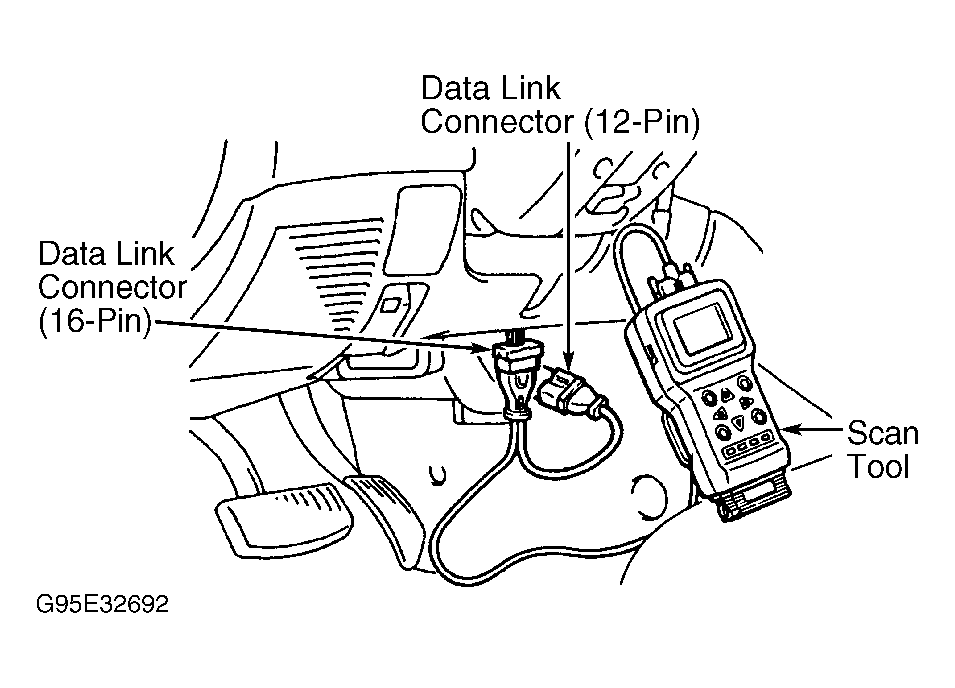
- Connect scan tool to Data Link Connector (DLC). See Fig 1
. Turn ignition on. Using scan tool, perform actuator test item No. 07 (FUEL PUMP). Sound of fuel pump operating should be heard when actuator test is performed. If fuel pump operates as specified, go to next step. If fuel pump does not perform as specified, problem is intermittent. Check for poor connections or faulty wiring for fuel pump control.
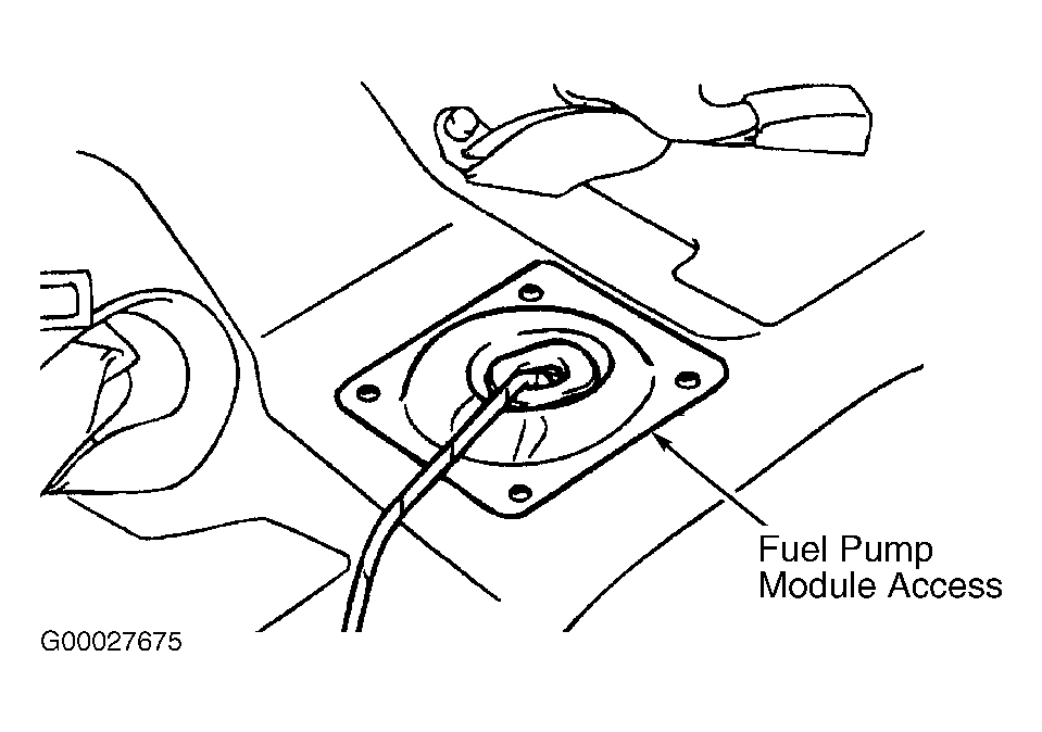
- Turn ignition off. Check for damage to fuel pump connector. Remove rear seat to access connector under cover. See Fig 2
.Repair as necessary. If fuel pump connector is okay, go to next step.
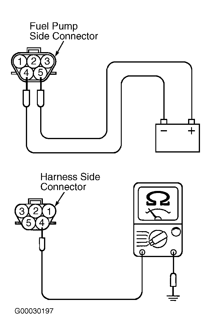
- Disconnect fuel pump connector. Connect a fused jumper wire between battery voltage and fuel pump connector terminal No. 5 (fuel pump side). Connect a second jumper wire between ground and fuel pump connector terminal No. 4 (fuel pump side). See Fig 3
. Sound of fuel pump operating should be heard when jumpers are connected. If fuel pump operates as specified, go to next step. If fuel pump does not perform as specified, replace fuel pump. See REMOVAL, OVERHAUL & INSTALLATION - CARS article.
- Using DVOM, measure resistance between ground and fuel pump harness connector terminal No. 4 (Black wire). See Fig 3
. If resistance is 2 ohms or less, go to next step. If resistance is greater than 2 ohms, repair open in Black wire between ground and fuel pump.
- Remove fuel pump relay and check for damage at connector terminals. See Figure
.Repair as necessary. If fuel pump relay connector is okay, go to next step.
- Test fuel pump relay. See MULTIPORT FUEL INJECTION (MFI) RELAY & FUEL PUMP RELAY
under MOTORS, RELAYS & SOLENOIDS. Replace as necessary. If fuel pump relay is okay, go to next step.
- Turn ignition on. With fuel pump relay removed, using DVOM, measure voltage between ground and fuel pump relay connector terminals No. 3 and 4. See Figure
. If battery voltage is indicated, go to next step. If battery voltage is not indicated, repair battery supply circuit between ignition switch and fuel pump relay.
- Check for open, short to ground or poor connections between fuel pump relay connector terminal No. 1 and fuel pump connector terminal No. 5. Repair as necessary. If circuit is okay, go to next step.
- Turn ignition off. Check ECM connector C-111 (M/T) or PCM connector C-112 (A/T) for loose, damaged or corroded terminals. If faulty connections are found, repair connector. After repairs, recheck system operation. If connections are okay, go to next step.
- Disconnect ECM connector C-111 (M/T) or PCM connector C-112 (A/T). Turn ignition on. Using DVOM, measure voltage between ground, and ECM connector C-111 terminal or PCM connector C-112 terminal No. 21 (Black wire). See Figure
or Figure
. If battery voltage is indicated, replace ECM/PCM. See REMOVAL, OVERHAUL & INSTALLATION - CARS article. If battery voltage is not indicated, repair open in Black wire between fuel pump relay connector terminal No. 2 and ECM/PCM.
 Courtesy of CHRYSLER CORP.
 Courtesy of DAIMLERCHRYSLER CORPORATION
 Courtesy of DAIMLERCHRYSLER CORPORATION