DTC P0505: Idle Air Control Motor Circuits: Testing
- Start engine and let idle. If engine will not idle, hold throttle open slightly to keep engine running. Using scan tool, actuate Idle Air Control (IAC) motor to 1400 RPM. Release throttle if holding open. Engine speed should be 1300-1500 RPM. If engine speed is as specified, go to next step. If engine speed is not as specified, go to step 6
.
- Using scan tool, actuate IAC motor to 900 RPM. Engine speed should be 800-1000 RPM. If engine speed is as specified, go to next step. If engine speed is not as specified, go to step 6
.
- With engine idling, using scan tool, perform IAC wiggle test. Idle speed should raise and lower with scan tool display. If engine speed raised and lowered with scan tool display, go to next step. If engine speed does not raise and lower with scan tool display, go to step 6
.
- Turn ignition off. Inspect wiring and connectors for damage. If wiring and connectors are okay, go to next step. If wiring and connectors are not okay, repair or replace as necessary.
- Start engine. Using scan tool in systems tests, perform IAC wiggle test. Wiggle wiring harness between IAC motor and Powertrain Control Module (PCM). PCM is located to left of Power Distribution Center (PDC) in engine compartment, next to air cleaner. Observe IAC motor for any interruptions in operation. If IAC does not stop operating at any time, test is complete. If IAC stopped operating at any time, repair wiring harness as necessary where wiggling cause problem to appear.
- Turn ignition off. Inspect wiring and connectors for damage. If wiring and connectors are okay, go to next step. If wiring and connectors are not okay, repair or replace as necessary.
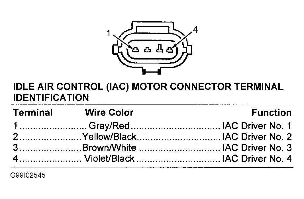
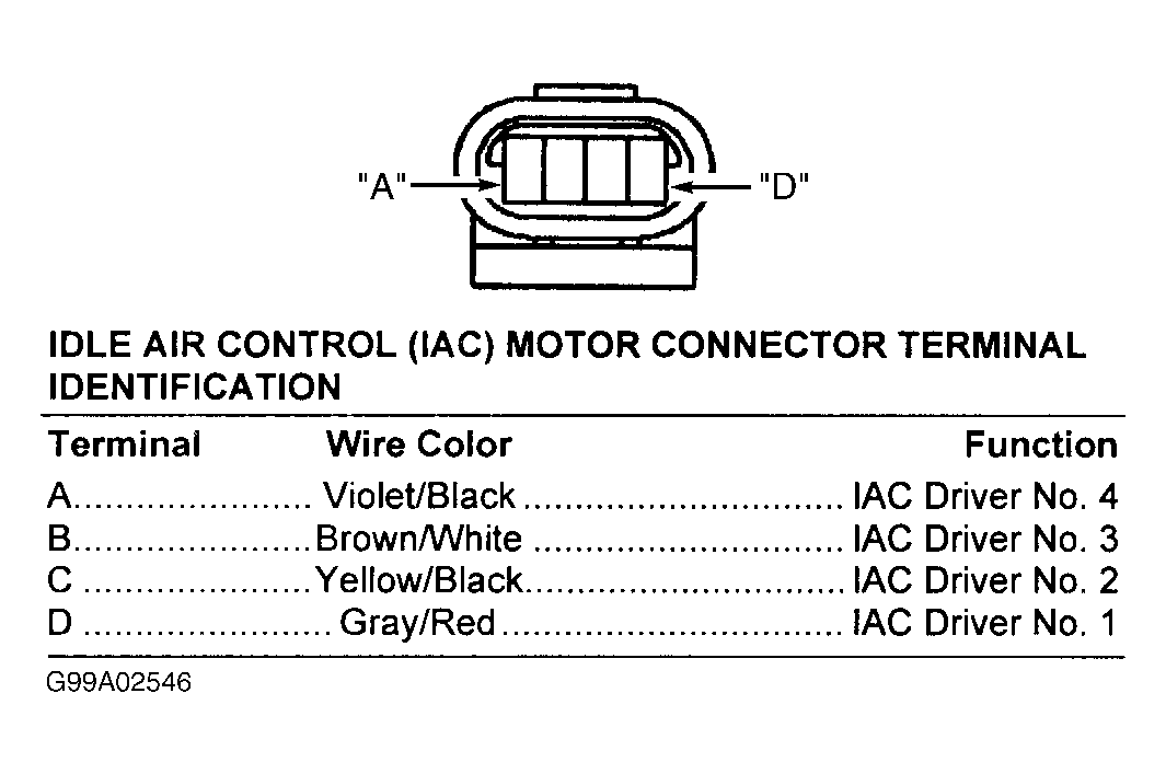
- Disconnect IAC motor harness connector. Inspect harness connector and clean/repair as necessary. Start engine and let idle. Measure voltage at Gray/Red wire terminal (terminal No. 1 on 2.0L/2.4L models; terminal "D" on 2.5L models) at IAC motor harness connector. See Fig 1
or Fig 2
. If voltage is not more than 5 volts at any time, go to next step. If voltage is more than 5 volts at any time, go to step 9
.
- Turn ignition off. Measure resistance between ground and Gray/Red wire terminal (terminal No. 1 on 2.0L/2.4L models; terminal "D" on 2.5L models) at IAC motor harness connector. If resistance is 5 ohms or more, go to step 14
. If resistance is less than 5 ohms, repair short to ground in Gray/Red wire between IAC motor and Powertrain Control Module (PCM).
- Measure voltage at Yellow/Black wire terminal (terminal No. 2 on 2.0L/2.4L models; terminal "C" on 2.5L models) at IAC motor harness connector. If voltage is not more than 5 volts at any time, go to next step. If voltage is more than 5 volts at any time, go to step 12
.
- Turn ignition off. Measure resistance between ground and Yellow/Black wire terminal (terminal No. 1 on 2.0L/2.4L models; terminal "D" on 2.5L models) at IAC motor harness connector. If resistance is 5 ohms or more, go to step 13
. If resistance is less than 5 ohms, repair short to ground in Yellow/Black wire between IAC motor and Powertrain Control Module (PCM).
- Turn ignition off. Measure resistance between ground and Brown/White wire terminal (terminal No. 3 on 2.0L/2.4L models; terminal "B" on 2.5L models) at IAC motor harness connector. If resistance is 5 ohms or more, go to step 25
. If resistance is less than 5 ohms, repair short to ground in Brown/White wire between IAC motor and PCM.
- Measure voltage at Brown/White wire terminal (terminal No. 3 on 2.0L/2.4L models; terminal "B" on 2.5L models) at IAC motor harness connector. If voltage is not more than 5 volts at any time, go to step 11
. If voltage is more than 5 volts at any time, go to step 16
.
- Ensure ignition is off. Disconnect Powertrain Control Module (PCM) harness connectors. PCM is located to left of Power Distribution Center (PDC) in engine compartment, next to air cleaner. Inspect harness connector and clean/repair as necessary. Measure resistance in Yellow/Black wire between IAC motor harness connector and terminal No. 49 at PCM harness connector C2. See Figure
. If resistance is less than 5 ohms, go to step 23
. If resistance is 5 ohms or more, repair open in Yellow/Black wire between IAC motor and PCM.
- Ensure ignition is off. Disconnect Powertrain Control Module (PCM) harness connectors. PCM is located to left of Power Distribution Center (PDC) in engine compartment, next to air cleaner. Inspect harness connector and clean/repair as necessary. Measure resistance in Gray/Red wire between IAC motor harness connector and terminal No. 57 at PCM harness connector C2. See Figure
. If resistance is less than 5 ohms, go to step 23
. If resistance is 5 ohms or more, repair open in Gray/Red wire between IAC motor and PCM.
- Turn ignition off. Measure resistance between ground and Violet/Black wire terminal (terminal No. 4 on 2.0L/2.4L models; terminal "A" on 2.5L models) at IAC motor harness connector. If resistance is 5 ohms or more, go to step 22
. If resistance is less than 5 ohms, repair short to ground in Brown/White wire between IAC motor and PCM.
- Measure voltage at Violet/Black wire terminal (terminal No. 4 on 2.0L/2.4L models; terminal "A" on 2.5L models) at IAC motor harness connector. If voltage is not more than 5 volts at any time, go to step 15
. If voltage is more than 5 volts at any time, go to next step.
- Ensure ignition is off. Disconnect Powertrain Control Module (PCM) harness connectors. PCM is located to left of Power Distribution Center (PDC) in engine compartment, next to air cleaner. Inspect PCM harness connector C2 and wiring for corroded, damaged, pushed out or miswired terminals. If connector and wiring are okay, go to next step. If connector and wiring are not okay, repair as necessary.
- Measure resistance between terminal No. 57 (Gray/Red wire) and terminals No. 48 (Brown/White wire), No. 49 (Yellow/Black wire) and No. 58 (Violet/Black wire) at PCM harness connector C2. See Figure
. If all resistances are 5 ohms or more, go to next step. If any resistance is less than 5 ohms, repair short between appropriate IAC motor driver circuits.
- Measure resistance between terminal No. No. 49 (Yellow/Black wire) and terminals No. 48 (Brown/White wire) and No. 58 (Violet/Black wire) at PCM harness connector C2. If both resistances are 5 ohms or more, go to next step. If either resistance is less than 5 ohms, repair short between appropriate IAC motor driver circuits.
- Measure resistance between terminals No. 48 (Brown/White wire) and No. 58 (Violet/Black wire) at PCM harness connector C2. If resistance is 5 ohms or more, go to next step. If resistance is less than 5 ohms, repair short between IAC motor No. 3 driver circuit (Brown/White wire) and IAC motor No. 4 driver circuit (Violet/Black wire).
- If no other potential causes are remaining, replace IAC motor.
- Ensure ignition is off. Disconnect Powertrain Control Module (PCM) harness connectors. PCM is located to left of Power Distribution Center (PDC) in engine compartment, next to air cleaner. Inspect harness connector and clean/repair as necessary. Measure resistance in Violet/Black wire between IAC motor harness connector and terminal No. 58 at PCM harness connector C2. See Figure
. If resistance is less than 5 ohms, go to next step. If resistance is 5 ohms or more, repair open in Violet/Black wire between IAC motor and PCM.
- Inspect PCM harness connector C2 and wiring for corroded, damaged, pushed out or miswired terminals. If connector and wiring are okay, go to next step. If connector and wiring are not okay, repair as necessary.
- If no other potential causes are remaining, replace PCM. After replacing PCM, PCM MUST be reprogrammed. See POWERTRAIN CONTROL MODULE
under PROGRAMMING.
- Ensure ignition is off. Disconnect Powertrain Control Module (PCM) harness connectors. PCM is located to left of Power Distribution Center (PDC) in engine compartment, next to air cleaner. Inspect harness connector and clean/repair as necessary. Measure resistance in Brown/White wire between IAC motor harness connector and terminal No. 48 at PCM harness connector C2. See Figure
. If resistance is less than 5 ohms, go to step 23
. If resistance is 5 ohms or more, repair open in Brown/White wire between IAC motor and PCM.
 Courtesy of DAIMLERCHRYSLER CORPORATION
 Courtesy of DAIMLERCHRYSLER CORPORATION