Tank, Fuel: Installation: Installation
 Courtesy of CHRYSLER GROUP, LLC
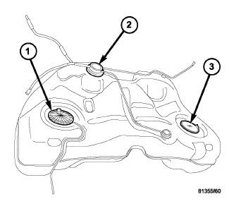
- If removed, install the fuel pump modules (1 and 3). Refer to MODULE, FUEL PUMP, INSTALLATION .
 Courtesy of CHRYSLER GROUP, LLC
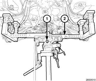
- Using a suitable hydraulic jack (1) and a fuel tank adapter (2), support the fuel tank.
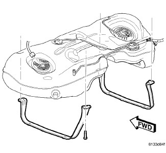
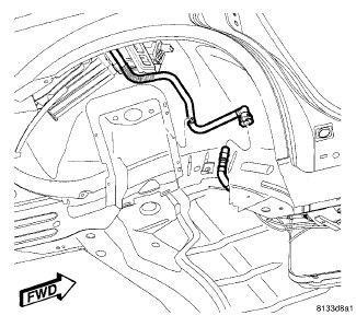
- Carefully raise the fuel tank into position while guiding the ORVR vent line through bracket.
 Courtesy of CHRYSLER GROUP, LLC
- Position the fuel tank support straps.
 Courtesy of CHRYSLER GROUP, LLC
- Install fuel tank support strap retaining bolts and tighten to 27 N.m (20 ft. lbs.).
 Courtesy of CHRYSLER GROUP, LLC
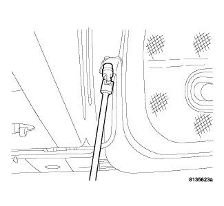
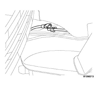
- Connect the vapor line.
 Courtesy of CHRYSLER GROUP, LLC
- Connect the EVAP line in the right rear wheel well.
 Courtesy of CHRYSLER GROUP, LLC
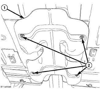
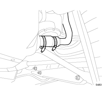
- Position the heat shield (1) and install the heat shield retainers (2).
- Install the fuel filter/water separator assembly. Refer to SEPARATOR AND FILTER, FUEL AND WATER, INSTALLATION .
- Install the propeller shaft. Refer to INSTALLATION
.
- Install the muffler and tailpipe assembly. Refer to MUFFLER, EXHAUST, INSTALLATION
.
 Courtesy of CHRYSLER GROUP, LLC
- Connect the fuel filler tube to the rubber hose on the fuel tank.
 Courtesy of CHRYSLER GROUP, LLC
- Install the hose clamp to the rubber hose connecting the fuel filler tube to the fuel tank and tighten the clamp to 4 N.m (35 in. lbs.).
 Courtesy of CHRYSLER GROUP, LLC
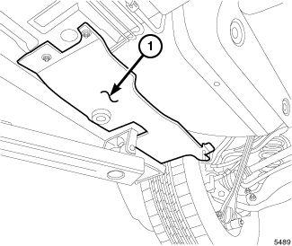
- Install the right underbody splash shield (1).
 Courtesy of CHRYSLER GROUP, LLC
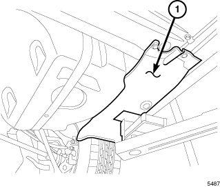
- Install the left underbody splash shield (1).
 Courtesy of CHRYSLER GROUP, LLC
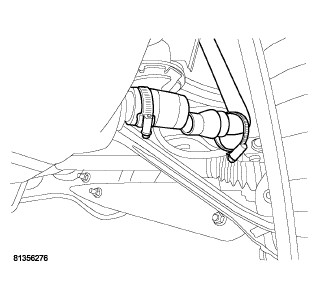
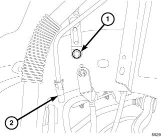
- Connect the ORVR vent line (2).
- Install the fuel filler tube retaining bolt (1) and tighten to 7 N.m (62 in. lbs.).
 Courtesy of CHRYSLER GROUP, LLC
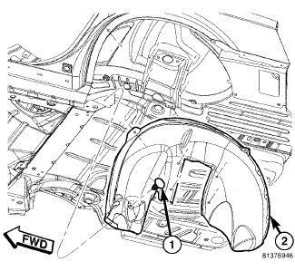
- Position the left rear wheelhouse splash shield (2).
- Install the push-pins (1) that secure the rear wheelhouse shield to the body.
- Install the left rear tire.
- Lower the vehicle.
- Fill the fuel tank.
- Connect the negative battery cable.
- Use the scan tool to pressurize the fuel system and check for leaks.