- Install the steering gear (3) on the front suspension crossmember (4). Install the four gear mounting bolts. Tighten the mounting bolts to 61 N.m (45 ft. lbs.).
- Center the power steering gear rack in its travel.
 Courtesy of CHRYSLER LLC
| 1 - SEAL |
| 2 - PINION SHAFT |
| 3 - TAB |
| 4 - POWER STEERING GEAR |
- Install the pinion shaft dash cover seal (1) over the power steering pinion shaft and onto the power steering gear housing (4). Align the holes on each side of the seal with the tabs (3) cast into the power steering gear housing.
 Courtesy of CHRYSLER LLC
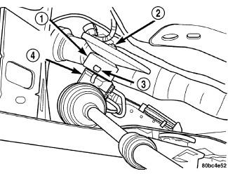
| 1 - STEERING COLUMN LOWER COUPLING |
| 2 - POWER STEERING GEAR PINION SHAFT |
| 3 - ROLL PIN |
| 4 - ROLL PIN PUNCH |
- Push the column end of the steering column lower coupling (1) partway up through the hole in the dash panel, then match the flat on the inside of the coupling to the flat on the power steering gear pinion shaft and slide the coupling onto the shaft.
- Align the roll pin hole in the coupling to the notch in the gear pinion shaft and install the roll pin (3) through the coupling until it is centered.
- Re-center the power steering gear rack in its travel as necessary.
 Courtesy of CHRYSLER LLC
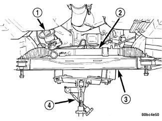
| 1 - STEERING COLUMN LOWER COUPLING |
| 2 - POWER STEERING GEAR |
| 3 - FRONT SUSPENSION CROSSMEMBER |
| 4 - TRANSMISSION JACK |
- Using the transmission jack (4), raise the front suspension crossmember and power steering gear until the crossmember contacts its mounting spot against the body and frame rails of the vehicle. As the crossmember is raised, carefully guide the steering column lower coupling (1) up through its hole in the dash panel.
- Start the two crossmember mounting bolts through the lower control arm rear isolator bushings into the tapping plates mounted in the body. Next, install the two front and the two rear mounting bolts attaching front suspension crossmember to frame rails of vehicle. Lightly tighten all six mounting bolts to approximately 2 N.m (20 in. lbs.) to hold the front suspension crossmember in position at this time.
NOTE:
When installing the front suspension crossmember back in the vehicle, it is very important that the crossmember be attached to the body in exactly the same spot as when it was removed. Otherwise, the vehicle's wheel alignment settings (caster and camber) will be lost.
 Courtesy of CHRYSLER LLC
- Using a soft face hammer, tap the front suspension crossmember back-and-forth or side-to-side until it is aligned with the previously made positioning marks (3) on the body of the vehicle. Once the front suspension crossmember is correctly positioned, tighten the two crossmember mounting bolts through the lower control arm rear isolator bushings to a torque of 250 N.m (185 ft. lbs.), then tighten the four remaining crossmember mounting bolts to a torque of 153 N.m (113 ft. lbs.).
 Courtesy of CHRYSLER LLC
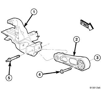
- Install the engine torque strut (2) to the crossmember (1). To properly align and tighten the torque strut. Refer to Engine/Engine Mounting/STRUT, Torque - Adjustments
.
 Courtesy of CHRYSLER LLC
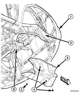
- Position the drive-belt splash shield (3) and install the fasteners (4) securing it to the body (2).
- Install the fastener (5) securing the drive belt splash shield (3) to the front suspension crossmember (6).
- If previously removed, install the fasteners securing the front fascia (1) to the body lower reinforcement.
 Courtesy of CHRYSLER LLC
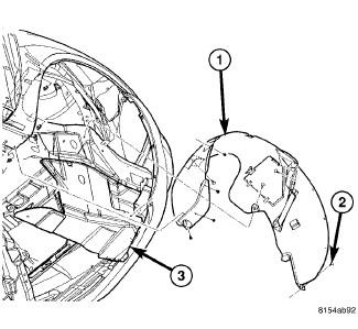
- Install the one fastener (2) securing the wheel house splash shield (1) to the drive belt splash shield (3).
 Courtesy of CHRYSLER LLC
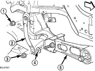
| 1 - NUT |
| 2 - PENCIL STRUT |
| 3 - NUT |
| 4 - FLAT WASHER |
| 5 - LOWER TORQUE STRUT |
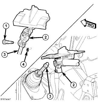
- Install the washer (4) on the end of the stud extending from the torque strut bolt at the crossmember.
- Position the pencil strut (2) on the right front corner of the crossmember and body of the vehicle and install the mounting nuts (1, 3). Tighten the nuts to 52 N.m (38 ft. lbs.).
- Using a lint free towel, wipe clean the open power steering hose ends and the power steering gear ports. Replace the pressure hose used O-ring with new. Lubricate the O-ring with power steering fluid.
 Courtesy of CHRYSLER LLC
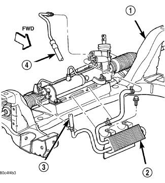
| 1 - CROSSMEMBER |
| 2 - COOLER |
| 3 - RETURN HOSE |
| 4 - PRESSURE HOSE |
- On vehicles equipped with crossmember mounted power steering fluid coolers:
- Place the cooler (2) in mounting position and snap the cooler tube going to the pump into the right routing clip on the front of the gear. Close the routing clip.
- Install the two screws securing the cooler to the front suspension crossmember (1). Tighten the screws to a torque of 10 N.m (90 in. lbs.).
Courtesy of CHRYSLER LLC
| 1 - CROSSMEMBER |
| 2 - COOLER |
| 3 - RETURN HOSE |
| 4 - PRESSURE HOSE |
- Non-turbo engine vehicles: Slide the cooler (2) hose onto the gear outlet port fitting. Secure the clamp on the hose past the bead on the steel fitting.
CAUTION:
On vehicles equipped with crossmember mounted power steering fluid coolers, forward of the steering gear, the power steering fluid pressure hose routes between the front suspension crossmember and the driveshaft. When tightening the pressure hose tube nut to the steering gear, the pressure hose must be positioned (clocked) such that its final routing (after tightened) offers 4-10 mm clearance to the front suspension crossmember (measured at the pressure hose steel-to-rubber coupling). There should be a clocking donut on the hose to preset this distance.
- Non-turbo engine vehicles: Insert the pressure hose (4) into its port on the power steering gear.
- Non-turbo engine vehicles: Thread the pressure hose tube nut into the gear. While making sure the pressure hose is not in contact with any vehicle components (see preceding caution), tighten the tube nut to 31 N.m (23 ft. lbs.).
 Courtesy of CHRYSLER LLC
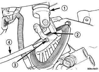
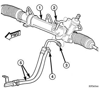
| 1 - POWER STEERING GEAR |
| 2 - ROUTING CLIP |
| 3 - PRESSURE HOSE TUBE NUT |
| 4 - RETURN HOSE CLAMP |
| 5 - PRESSURE/RETURN HOSE ASSEMBLY |
- Turbo engine vehicles: Slide the return hose onto the gear outlet port fitting. Secure the clamp (4) on the hose past the bead on the steel fitting.
- Turbo engine vehicles: Insert the pressure hose into its port on the power steering gear (1).
- Turbo engine vehicles: Thread the pressure hose tube nut into the gear, but do not tighten it at this time
.
- Turbo engine vehicles: Install routing clip (2) up from gear outlet tube onto fluid pressure hose tube.
- Turbo engine vehicles: Tighten the pressure hose tube nut to 31 N.m (23 ft. lbs.).
 Courtesy of CHRYSLER LLC
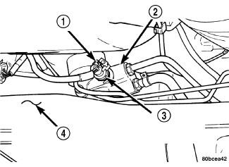
| 1 - WIRING HARNESS CONNECTOR |
| 2 - POWER STEERING GEAR |
| 3 - POWER STEERING FLUID PRESSURE SWITCH |
| 4 - REAR OF FRONT SUSPENSION CROSSMEMBER |
- If equipped with a power steering fluid pressure switch (3), connect the wiring harness connector (1) to the power steering fluid pressure switch (3). Be sure the locking tab on the wiring harness connector is securely latched following installation.
 Courtesy of CHRYSLER LLC
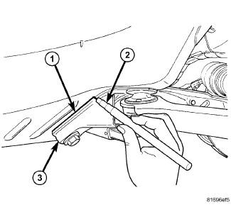
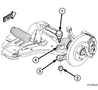
- On each side of vehicle, place the tie rod heat shield (4) on the knuckle arm (3) so that the shield is positioned straight away from the steering gear and tie rod end once installed. Align the hole in the shield with the tie rod end mounting hole.
- On each side of vehicle, install the outer tie rod (1) ball stud into the hole in the knuckle arm (3). Start the tie rod mounting nut (2) onto the stud. While holding the tie rod end stud with a wrench, tighten the nut with a wrench or crowfoot wrench. Tighten the nut to 55 N.m (40 ft. lbs.).
 Courtesy of CHRYSLER LLC
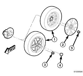
- On both sides of vehicle, install the tire and wheel assembly (1). Refer to Tires and Wheels - Installation
. Install and tighten wheel mounting nuts (3) to 135 N.m (100 ft. lbs.).
- Lower the vehicle.
- Position the dash-to-lower coupling seal in place over the lower coupling's plastic collar.
NOTE:
Verify that grease is present on the lip of the dash-to-coupling seal where it contacts the coupling's plastic collar.
 Courtesy of CHRYSLER LLC
- Verify the front wheels of vehicle are in the STRAIGHT-AHEAD position.
NOTE:
Do not tighten the coupling pinch bolt anytime the vehicle is not at curb riding height. It may cause unwanted conditions within the steering column if the vehicle is suspended in any manner when the pinch bolt is tightened.
- If necessary, rotate the steering column shaft until the upper coupling (2) lines up with the rounded side of the lower coupling (3).
- Slide the upper coupling (2) over the end of the lower coupling (3) and install the pinch bolt (1). Tighten the pinch bolt nut to 28 N.m (250 in. lbs.).
- Install the pinch bolt retainer clip (4).
- Remove the steering wheel holder.
- While looking under the instrument panel at the lower coupling, rotate the steering wheel back-and-forth to verify that the lower coupling does not squeak against the dash-to-coupling seal.
- Fill and bleed the power steering system. See Steering - Standard Procedure
- Check for fluid leaks.
- Adjust the front wheel toe setting. Refer to Front Suspension/Wheel Alignment - Standard Procedure