Trailing Link
 Courtesy of CHRYSLER LLC
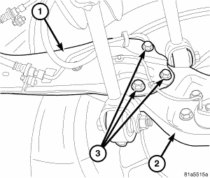
- Position the trailing link (1) and install the three bolts (3) securing the trailing link to the knuckle (2). Tighten the mounting bolts to 60 N.m (44 ft. lbs.).
 Courtesy of CHRYSLER LLC
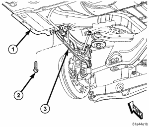
- Position the forward end of the trailing link (3) on the body (1) and install the two mounting bolts (2). Do not tighten the bolts at this time.
 Courtesy of CHRYSLER LLC
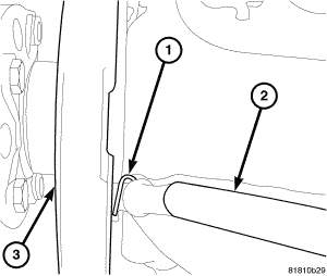
- Insert the parking brake cable through the trailing link from the inboard side.
- Slide the parking brake cable (2) into the brake support plate (3) with parking brake shoes.
- Install the hair pin (1) securing the parking brake cable (2) to the brake support plate (3).
 Courtesy of CHRYSLER LLC
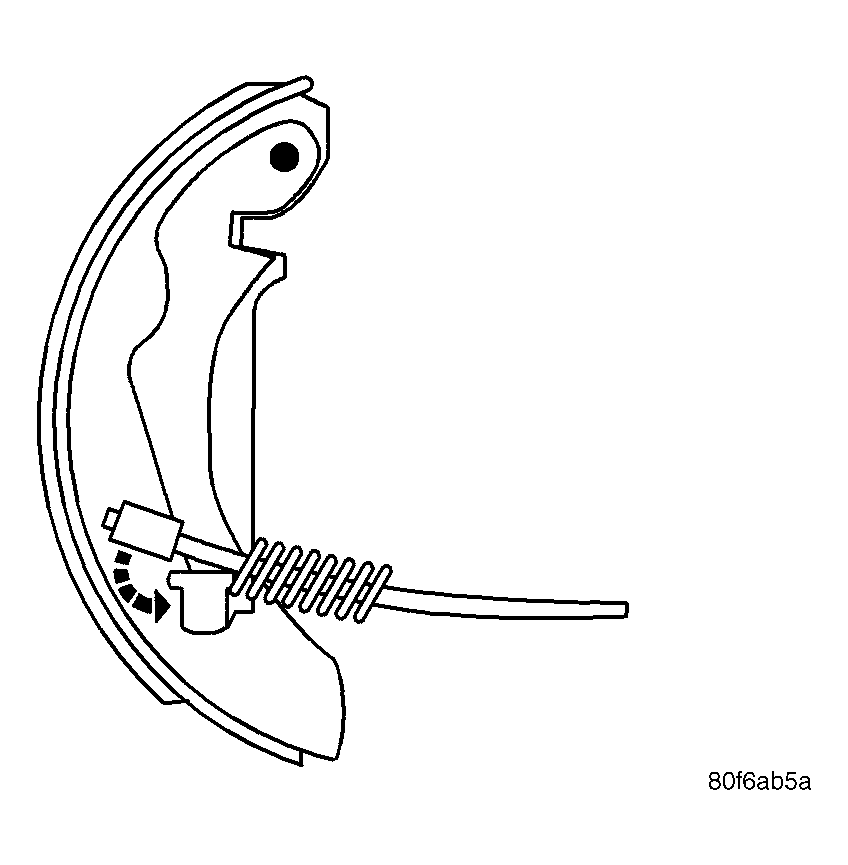
- Install the parking brake cable onto the lever on the parking brake shoe.
- Install the hub and bearing, then the brake rotor or brake drum over the hub and bearing. See REMOVAL .
 Courtesy of CHRYSLER LLC
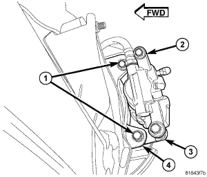
- If equipped with rear disc brakes, slide the disc brake caliper (2) and adapter (3) assembly over brake rotor and brake support plate.
- If equipped with rear disc brakes, install the two bolts (1) securing disc brake caliper adapter (3) to the brake support plate (4). Tighten the mounting bolts to 105 N.m (77 ft. lbs.).
 Courtesy of CHRYSLER LLC
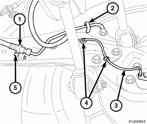
- If equipped, install the routing clips (4) fastening the wheel speed sensor (3) to the trailing link.
- Install the brake tube in the routing clip (2) on the trailing link.
- Position the brake flex hose and tube bracket (1) at the trailing link bracket and install the mounting screw (5). Tighten the screw to 23 N.m (17 ft. lbs.).
 Courtesy of CHRYSLER LLC
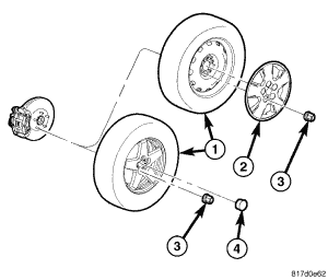
- Install tire and wheel assembly (1). Refer to INSTALLATION
. Install and tighten wheel mounting nuts (3) to 135 N.m (100 ft. lbs.).
- Lower the vehicle.
Courtesy of CHRYSLER LLC
- Position the vehicle on an alignment rack/drive-on lift. Raise the vehicle as necessary to access yet to be tightened mounting bolts.
- Tighten the two mounting bolts fastening the leading end of the trailing link (3) to the body (1) to 110 N.m (81 ft. lbs.).
- Perform wheel alignment as necessary. See STANDARD PROCEDURE .