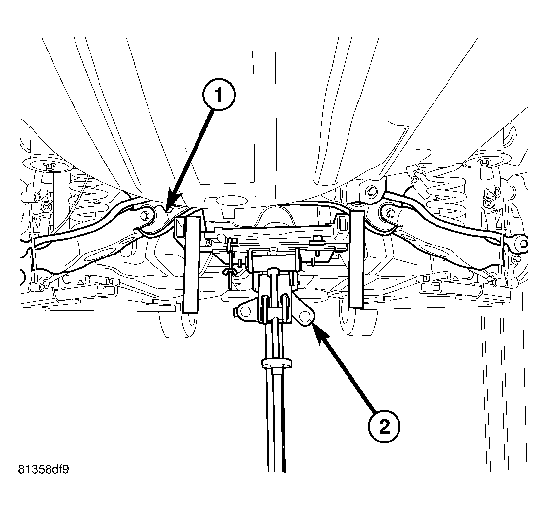
- Install rear crossmember (1) on jack (2) head in same position in which it was removed and secure in place.
 Courtesy of DAIMLERCHRYSLER CORP.
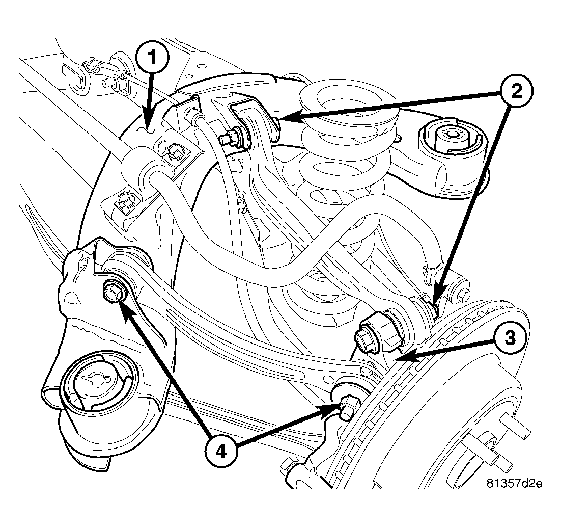
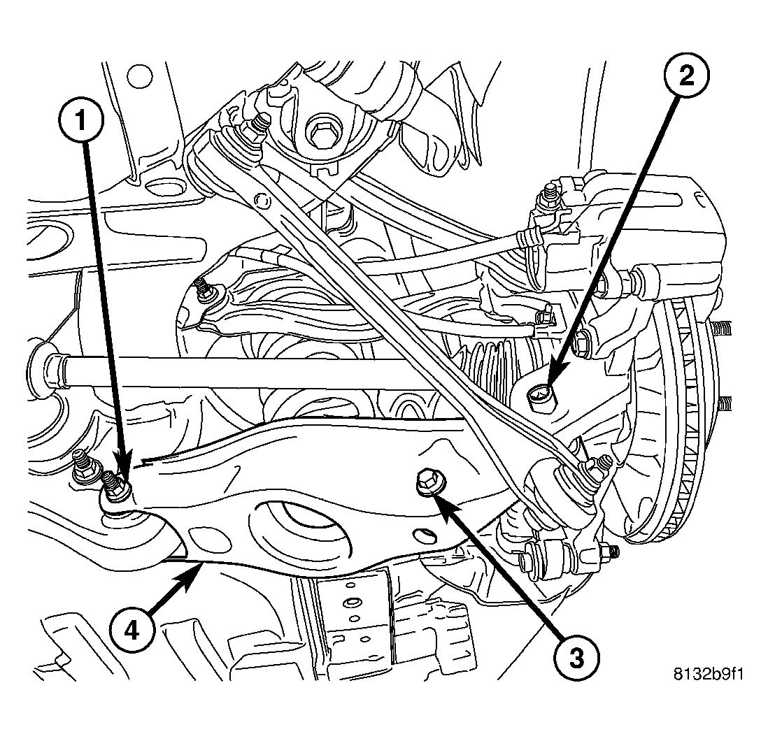
- Carefully place one side knuckle with links and parking brake cable attached as an assembly into mounted position on rear suspension crossmember. Install nut and bolt (2) mounting camber link to crossmember (1) to hold assembly in place. Do not tighten at this time.
- Carefully place opposite side knuckle with links and parking brake cable attached as an assembly into mounted position on rear suspension crossmember. Install nut and bolt (2) mounting camber link to crossmember (1) to hold assembly in place. Do not tighten at this time.
- On each side of crossmember, install nut and bolt (4) mounting each tension link to crossmember (1). Do not tighten at this time.
 Courtesy of DAIMLERCHRYSLER CORP.
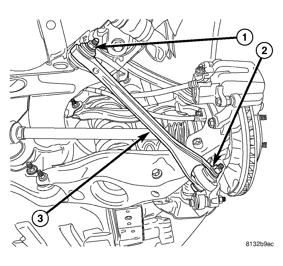
- On each side of crossmember, Install bolt and nut (1) mounting each compression link (3) at crossmember. Do not tighten at this time.
 Courtesy of DAIMLERCHRYSLER CORP.
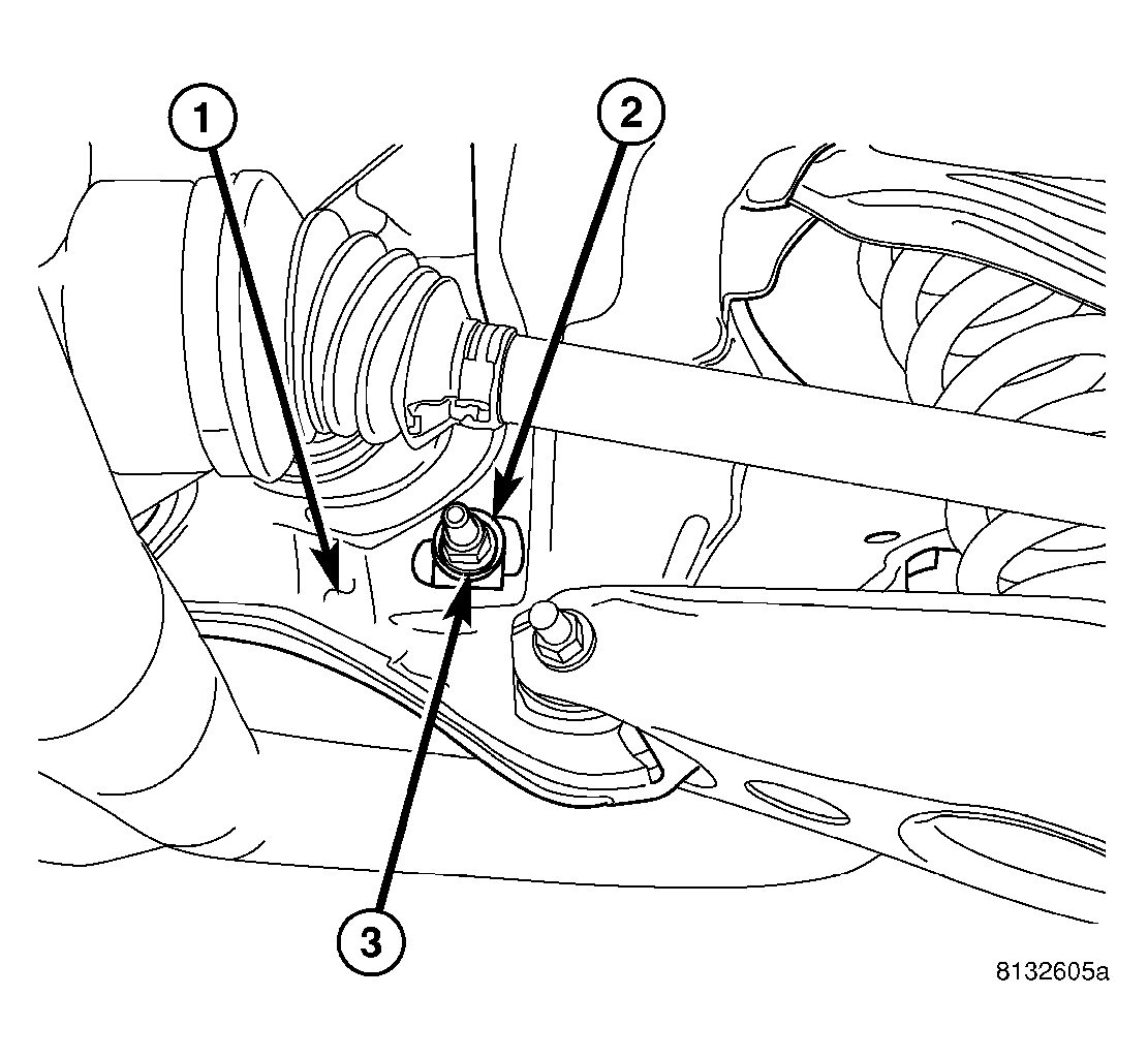
- On each side of crossmember, slide cam bolt (2) attaching toe link through crossmember and link (1) from rear.
 Courtesy of DAIMLERCHRYSLER CORP.
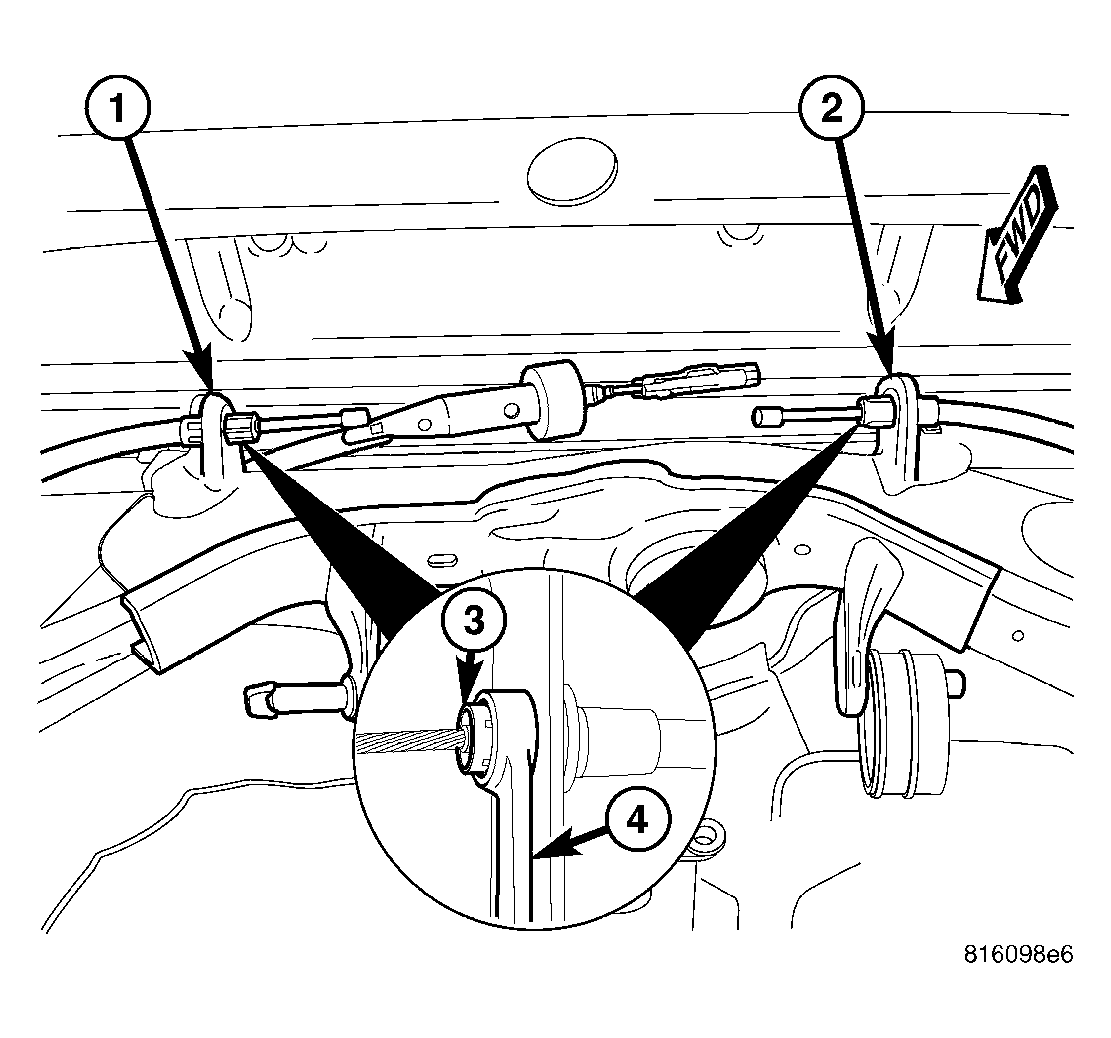
- On each side of crossmember, while holding toe adjustment cam bolt from rotating, install cam washer (2) and nut (3) securing toe link at crossmember (1). Do not tighten at this time.
 Courtesy of DAIMLERCHRYSLER CORP.
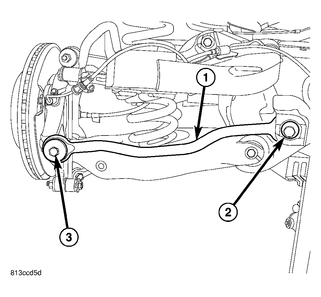
- On each side of crossmember, install bolt and nut (1) fastening spring link (4) to crossmember. Do not tighten at this time.
 Courtesy of DAIMLERCHRYSLER CORP.
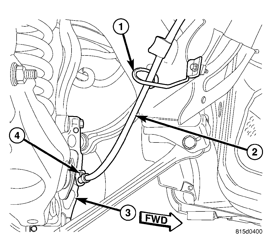
- On each side of crossmember rear, guide leading end of rear parking brake through crossmember bracket (1 - left)(2 - right) near equalizer and press cable housing retainer into bracket allowing retainer fingers to lock cable in place.
 Courtesy of DAIMLERCHRYSLER CORP.
- On each side of crossmember rear, install J-nut for parking brake cable guide.
- On each side, install screw fastening parking brake cable routing guide (1) to crossmember.
 Courtesy of DAIMLERCHRYSLER CORP.
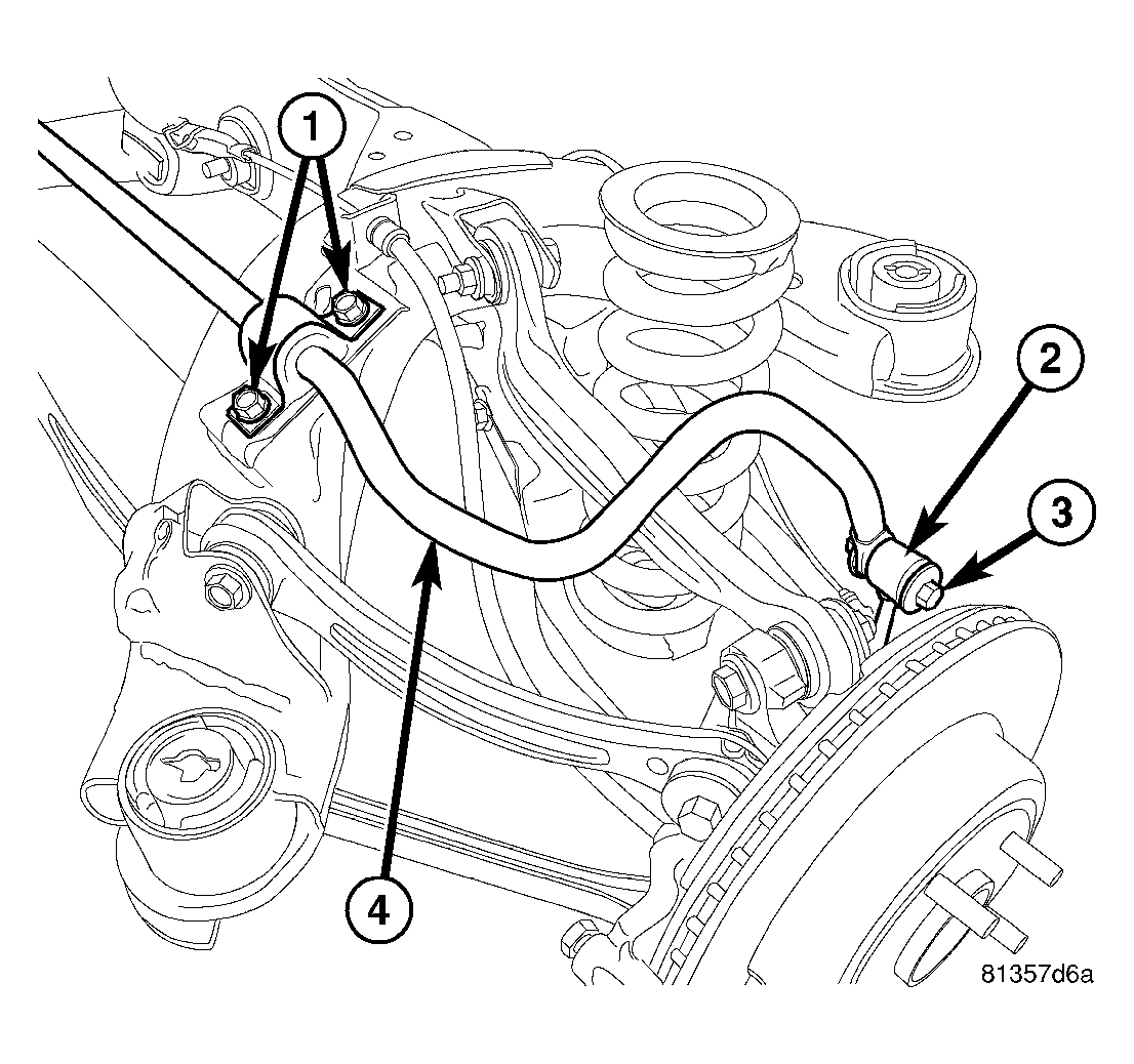
- Install stabilizer bar (4) with cushions and retainers on crossmember.
- Install cushion retainer mounting bolts (1). Do not tighten at this time.
- Install bolt (3) and nut fastening stabilizer bar ends to each stabilizer link (2). Do not tighten at this time.
- Tighten cushion retainer mounting bolts (1) to 60 N.m (44 ft. lbs.).
 Courtesy of DAIMLERCHRYSLER CORP.
CAUTION:
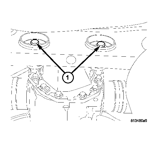
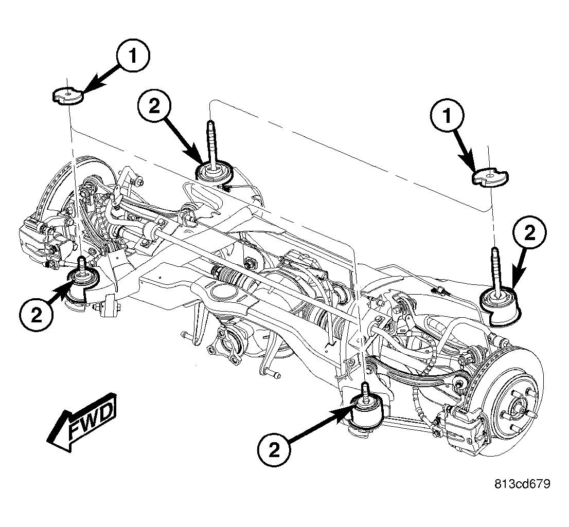
Differential mounting bolts (1) must be installed through bushings prior to crossmember installation in vehicle. Bolts cannot be inserted through bushings once crossmember is installed.
- Transfer differential mounting bolts (1) from original crossmember differential mount bushings to bushings in replacement crossmember. Install bolts from rear. Be sure to insert bolts through correct mount bushings in crossmember depending on rear axle differential (198 mm axle differential shown in Fig 10).
NOTE:
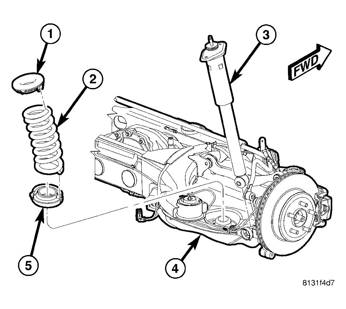
Do not install coil springs on spring links at this time.
 Courtesy of DAIMLERCHRYSLER CORP.
- Raise crossmember to body mounting points. As crossmember is raised, align shocks (3) with pockets in spring links. Do not install bolts at this time.
 Courtesy of DAIMLERCHRYSLER CORP.
NOTE:
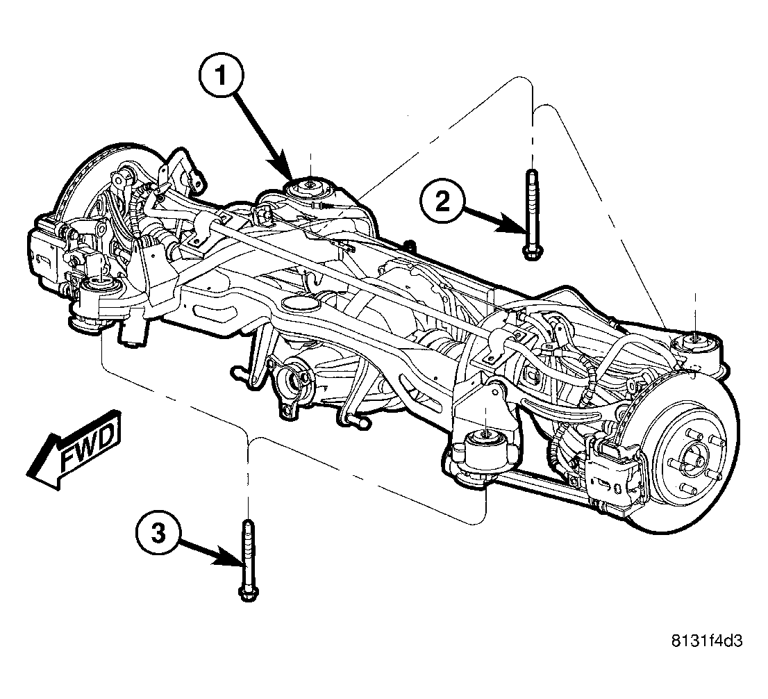
There are four crossmember mounting bolts. Rear mounting bolts (2) are longer than front mounting bolts (3). Do not interchange mounting bolts.
- Continue to raise crossmember (1) with jack until crossmember mounting bolts (2 and 3) can be installed. Install left side crossmember mounting bolts, but not the right side bolts. It is not necessary to tighten bolts at this point.
Courtesy of DAIMLERCHRYSLER CORP.
CAUTION:
To avoid damaging other components of vehicle, do not lower crossmember any further than necessary to install coil spring (2).
- Slowly
lower jack allowing right side of crossmember to drop. Do not lower jack at a fast rate.
Lower jack just enough to allow spring (2) Installation. Do not lower jack any further than necessary.
NOTE:
Before installing coil spring, make sure isolators (1 and 5) are completely installed on ends of spring.
- Install coil spring (2) with isolators into spring pocket of spring link fitting the lower isolator to the shape of the pocket, then align top of spring with body mount.
 Courtesy of DAIMLERCHRYSLER CORP.
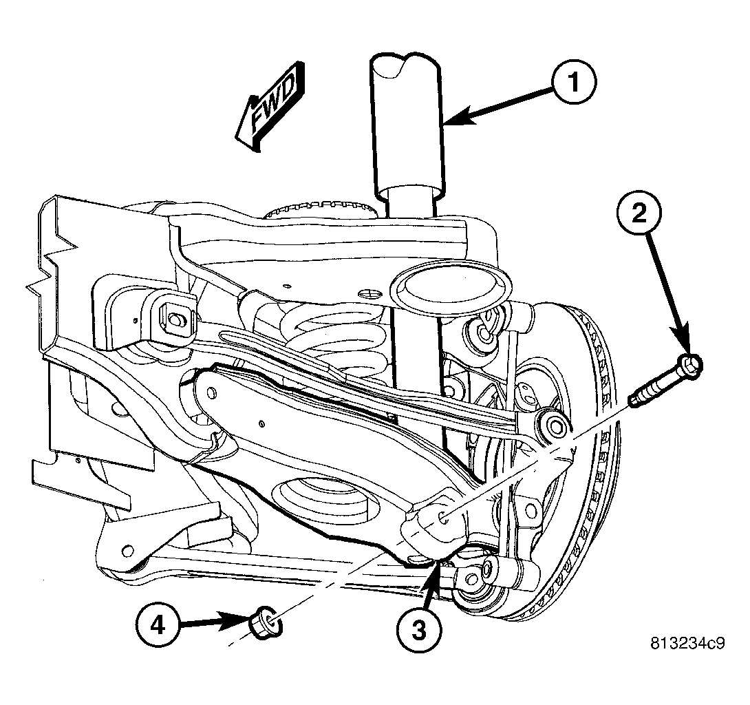
- Carefully raise jack, guiding coil spring and lower end of shock absorber (1) into mounted positions. Once shock absorber (1) lower mounting hole lines up with hole in spring link (3), stop jacking.
- Install lower shock mounting bolt (2) and nut (4). Do not tighten at this time.
 Courtesy of DAIMLERCHRYSLER CORP.
- If vehicle is equipped with AWD, insert spacers (1) on top of right crossmember mount bushings (2) before crossmember is raised into place.
Courtesy of DAIMLERCHRYSLER CORP.
NOTE:
There are four crossmember mounting bolts. Rear mounting bolts (2) are longer than front mounting bolts (3). Do not interchange mounting bolts.
- Raise right side of crossmember (1) into mounted position. Install right side crossmember mounting bolts (2 and 3). Snug, but do not fully tighten bolts at this time.
- Remove both front and rear crossmember mounting bolts (2 and 3) on left
side of vehicle.
Courtesy of DAIMLERCHRYSLER CORP.
CAUTION:
To avoid damaging other components of vehicle, do not lower crossmember any further than necessary to install coil spring (2).
- Slowly
lower jack allowing left side of crossmember to drop. Do not lower jack at a fast rate.
Lower jack just enough to allow spring (2) Installation. Do not lower jack any further than necessary.
NOTE:
Before installing coil spring, make sure isolators (1 and 5) are completely installed on ends of spring.
- Install coil spring (2) with isolators into spring pocket of spring link fitting the lower isolator to the shape of the pocket, then align top of spring with body mount.
Courtesy of DAIMLERCHRYSLER CORP.
- Carefully raise jack, guiding coil spring and lower end of shock absorber (1) into mounted positions. Once shock absorber (1) lower mounting hole lines up with hole in spring link (3), stop jacking.
- Install lower shock mounting bolt (2) and nut (4). Do not tighten at this time.
Courtesy of DAIMLERCHRYSLER CORP.
- If vehicle is equipped with AWD, insert spacers (1) on top of left crossmember mount bushings (2) before crossmember is raised into place.
Courtesy of DAIMLERCHRYSLER CORP.
NOTE:
There are four crossmember mounting bolts. Rear mounting bolts (2) are longer than front mounting bolts (3). Do not interchange mounting bolts.
- Raise left side of crossmember (1) into mounted position. Install left side crossmember mounting bolts (2 and 3). Snug, but do not fully tighten bolts at this time.
 Courtesy of DAIMLERCHRYSLER CORP.
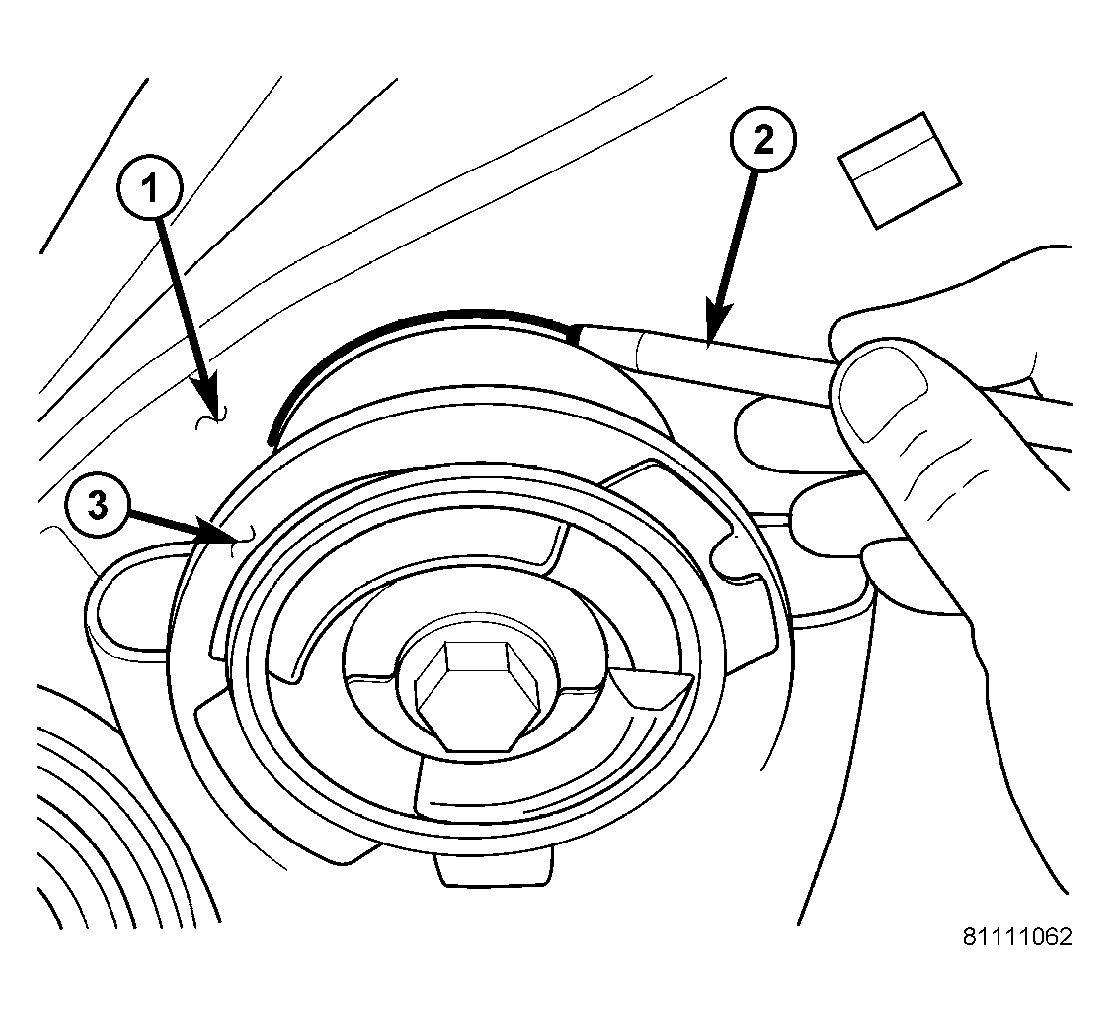
| 1 - BODY |
| 2 - MARKER (OR CRAYON) |
| 3 - CROSSMEMBER BUSHING FLANGE |
- Shift crossmember as necessary to line up mounts (3) with location marks drawn on body (1) before removal.
 Courtesy of DAIMLERCHRYSLER CORP.
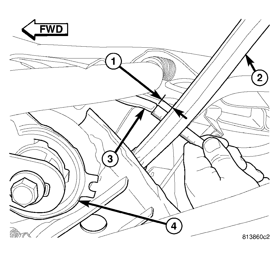
- Once mounts are lined up with location marks, on both sides of vehicle, measure distance (1) between the tension link (2) and weld flange (3) on body directly in front of it, just outboard of the front mount bushing (4). This distance must be at least 12 mm to allow proper clearance for suspension movement.
If distance is less than 12 mm on either side of vehicle, shift that side of rear crossmember directly rearward until distance is 12 mm or greater. To do so, loosen 3 mounting bolts slightly, leaving one on opposite side of shift snugged to pivot off of. Shift crossmember rearward and snug loosened bolts. Remeasure opposite side to be sure it still maintains minimum 12 mm distance.
Courtesy of DAIMLERCHRYSLER CORP.
- Tighten all four crossmember mounting bolts (2 and 3) to 180 N.m (133 ft. lbs.).
 Courtesy of DAIMLERCHRYSLER CORP.
- Remove jack (3) from under rear crossmember.
 Courtesy of DAIMLERCHRYSLER CORP.
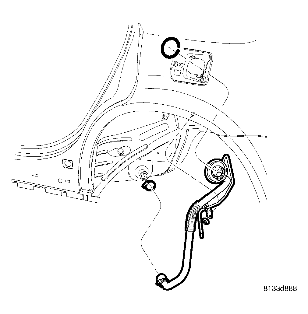
- Install fuel filler tube. (Refer to FUEL SYSTEM/FUEL DELIVERY/FUEL TANK FILLER TUBE - INSTALLATION)
 Courtesy of DAIMLERCHRYSLER CORP.
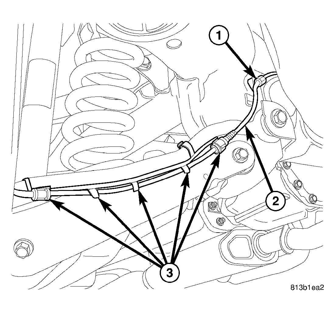
- Clip left rear wheel speed sensor cable (2) to routing clip (1) above toe link mount on rear crossmember.
 Courtesy of DAIMLERCHRYSLER CORP.
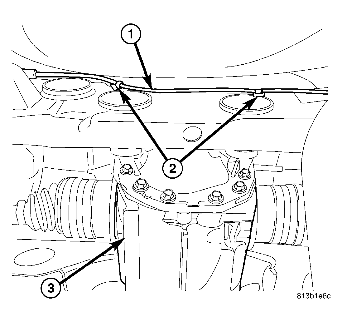
- Clip left rear wheel speed sensor cable (1) to routing clips (2) along rear of crossmember near rear differential (3).
 Courtesy of DAIMLERCHRYSLER CORP.
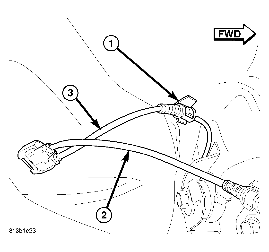
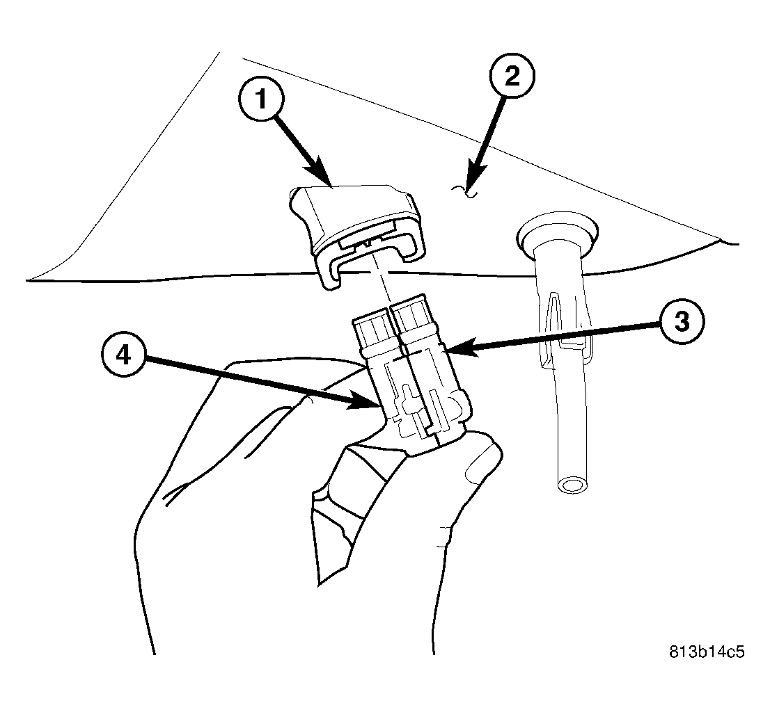
- Clip left rear wheel speed sensor cable (3) to routing clip (1) near body connector.
 Courtesy of DAIMLERCHRYSLER CORP.
- Match left rear wheel speed sensor connector (4) to right sensor connector (3) to make one connector.
- Insert speed sensor connectors (3 and 4) into body wiring harness connector (1) located in luggage compartment floor pan (2). When installing connector, make sure retaining clip on body connector is properly in place and sensor connector cannot be pulled out.
 Courtesy of DAIMLERCHRYSLER CORP.
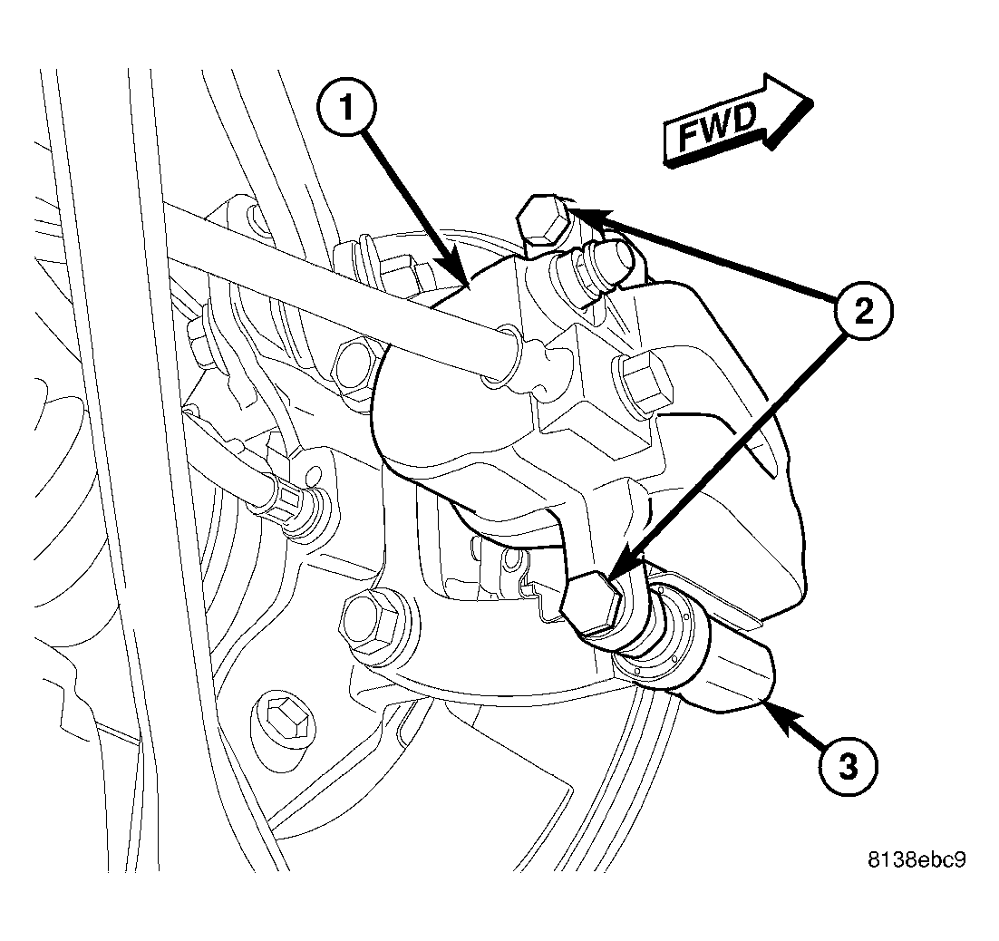
- If equipped with standard or premium disc brakes, on each rear disc brake:
- Push caliper guide pins into caliper adapter to clear caliper mounting bosses when installing.
- Guide caliper and brake hose down through rear suspension, then slide caliper over brake pads and onto caliper adapter (3).
CAUTION:
Extreme caution should be taken not to cross-thread caliper guide pin bolts (2) when they are installed.
- Align caliper mounting holes with guide pins, then install guide pin bolts (2). While holding guide pins from turning, tighten bolts to 31 N.m (23 ft. lbs.) torque.
- Make sure brake hose is properly routed and will not come in contact with suspension components.
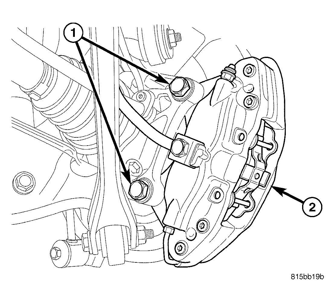
- If equipped with SRT8 disc brakes, at each rear disc brake, support spring link using a transmission jack or other appropriate jack as indicated in removal procedure. (Refer to FRAME & BUMPERS/FRAME/REAR CROSSMEMBER - REMOVAL)
 Courtesy of DAIMLERCHRYSLER CORP.
- If equipped with SRT8 disc brakes, on each rear disc brake, slide caliper with pads (2) over brake rotor and align with knuckle.
- If equipped with SRT8 disc brakes, on each rear disc brake, install caliper mounting bolts (1). Tighten bolts to 130 N.m (96 ft. lbs.).
- If equipped with SRT8 disc brakes, on each rear disc brake, remove jack from under spring link.
 Courtesy of DAIMLERCHRYSLER CORP.
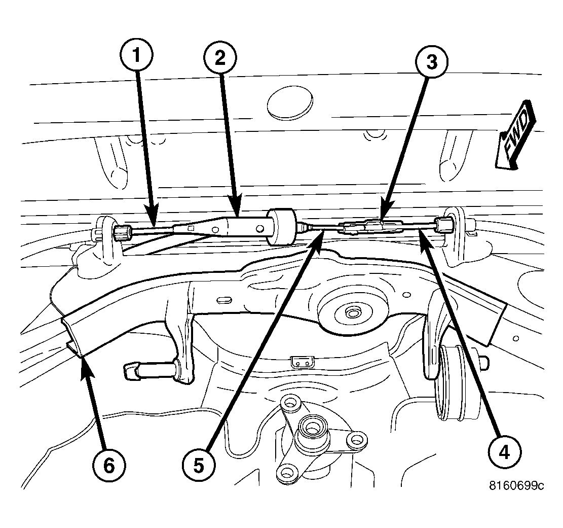
- Route front parking brake cable with equalizer above rear crossmember.
NOTE:
Due to short travel and low spring tension, it is not necessary to lock-out parking brake lever to service parking brake components.
- Connect left rear parking brake cable (1) to equalizer (2).
- Connect right rear parking brake cable (4) to connector (3) already attached to front parking brake cable (5).
 Courtesy of DAIMLERCHRYSLER CORP.
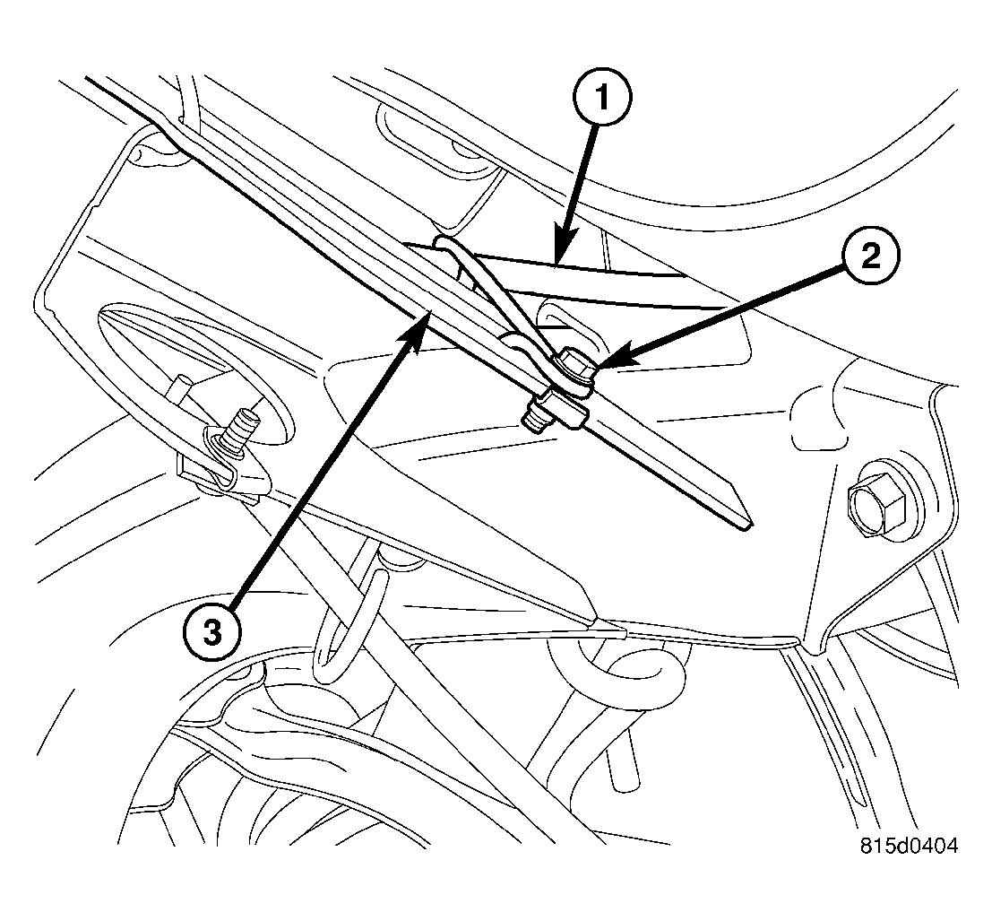
- Install J-nut for mounting parking brake cable routing bracket to crossmember.
- Insert front parking brake cable routing bracket locating pin into front flange of crossmember (3), then install screw (2) fastening cable (1) routing bracket to rear crossmember.
 Courtesy of DAIMLERCHRYSLER CORP.
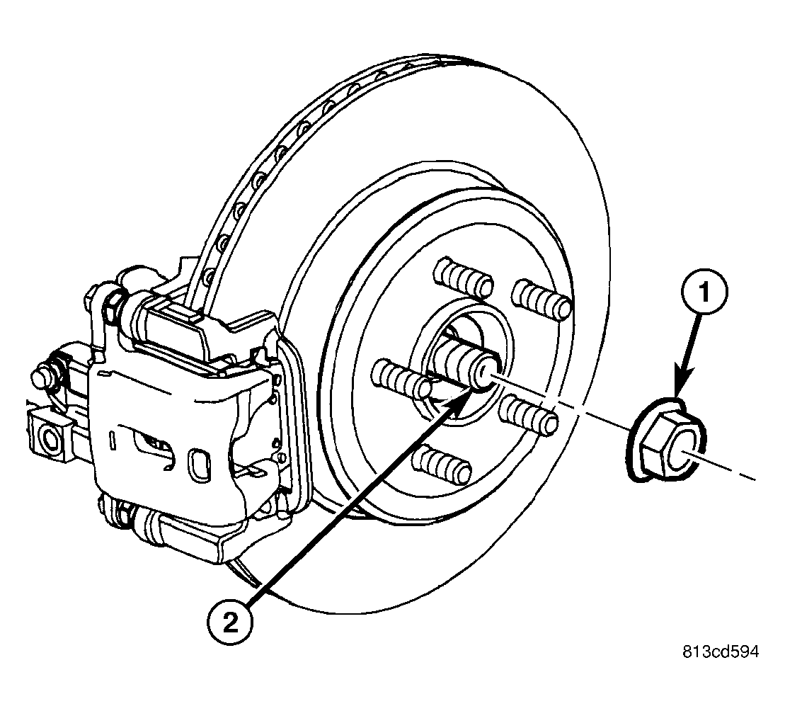
- On each side of vehicle, slide an axle half shaft (2) through hub and bearing and install hub nut (1). Do not tighten hub nuts at this time.
- Install rear axle differential. (Refer to DIFFERENTIAL & DRIVELINE/REAR AXLE - 198MM - INSTALLATION)(Refer to DIFFERENTIAL & DRIVELINE/REAR AXLE - 210MM - INSTALLATION)(Refer to DIFFERENTIAL & DRIVELINE/REAR AXLE - 215RII - INSTALLATION)
Courtesy of DAIMLERCHRYSLER CORP.
- While a helper applies brakes to keep hub from turning, tighten hub nut to 213 N.m (157 ft. lbs.).
 Courtesy of DAIMLERCHRYSLER CORP.
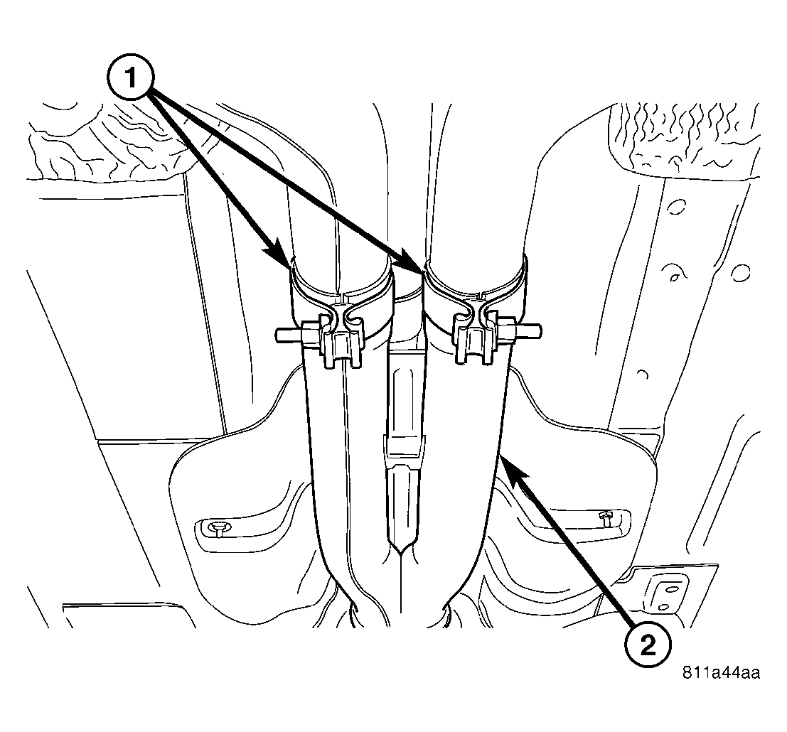
- Install rear exhaust system (2) (dual-outlet exhaust shown in Fig 36).
(Refer to EXHAUST SYSTEM
)
 Courtesy of DAIMLERCHRYSLER CORP.
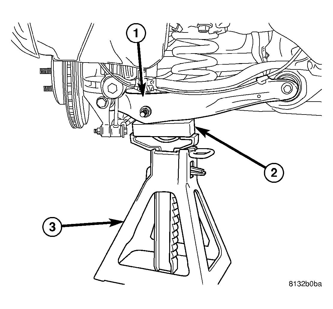
- Lower vehicle until front tires contact floor but rear is still suspended. Place jack stands under each rear suspension spring link. Place an appropriate wooden block between stand and link to avoid damaging spring link, then lower vehicle until full vehicle weight is supported by suspension.
Courtesy of DAIMLERCHRYSLER CORP.
- Tighten camber link bolt (2) at crossmember to 85 N.m (63 ft. lbs.).
- Tighten tension link bolt nut (2) at crossmember to 85 N.m (63 ft. lbs.).
Courtesy of DAIMLERCHRYSLER CORP.
- Tighten compression link bolt (2) at crossmember to 85 N.m (63 ft. lbs.) torque.
Courtesy of DAIMLERCHRYSLER CORP.
- Tighten spring link bolt (1) at crossmember to 108 N.m (80 ft. lbs.).
Courtesy of DAIMLERCHRYSLER CORP.
- Tighten shock absorber lower mounting bolt nut (4) to 72 N.m (53 ft. lbs.).
Courtesy of DAIMLERCHRYSLER CORP.
- Tighten stabilizer link bolts (3) to 61 N.m (45 ft. lbs.).
Courtesy of DAIMLERCHRYSLER CORP.
- Raise vehicle and remove jack stands (3).
 Courtesy of DAIMLERCHRYSLER CORP.
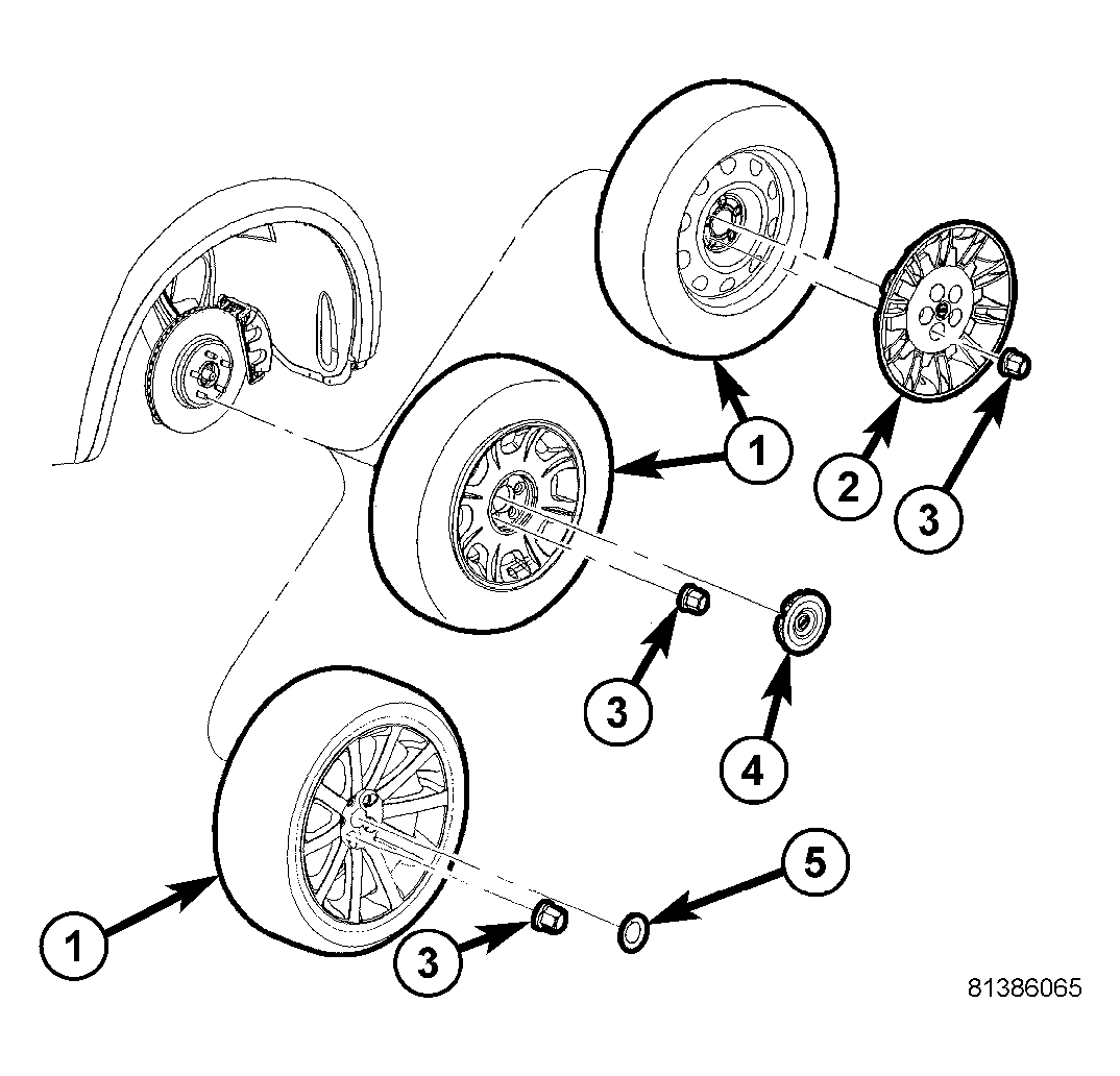
- Install tire and wheel assemblies (1). Tighten wheel mounting nuts (3) to 150 N.m (110 ft. lbs.). (Refer to TIRES/WHEELS - INSTALLATION)
- Lower vehicle.
 Courtesy of DAIMLERCHRYSLER CORP.
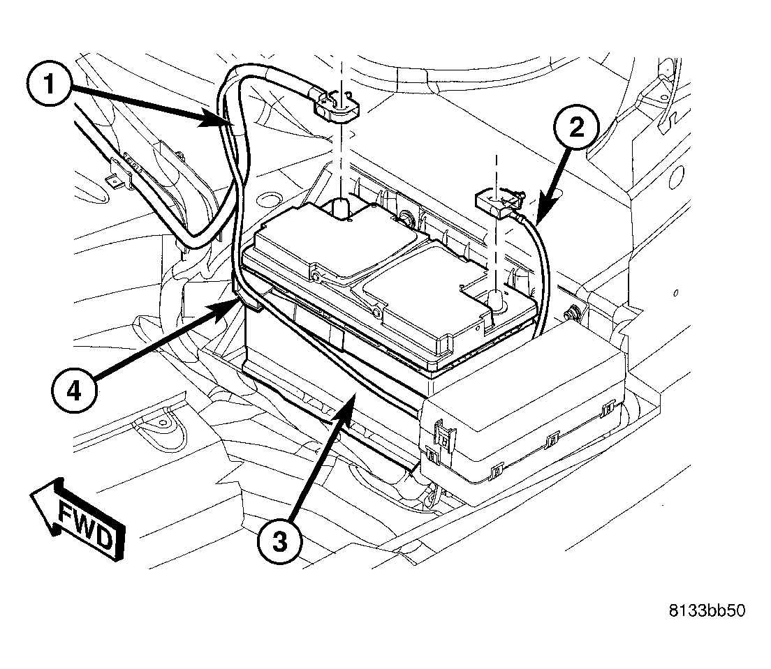
- Connect battery negative cable (2) to battery post. It is important that this is performed properly. (Refer to ELECTRICAL/BATTERY SYSTEM - STANDARD PROCEDURE)
- Pump brake pedal several times to ensure vehicle has a firm brake pedal before moving vehicle.
- Perform wheel alignment, paying special attention to thrust angle. If rear crossmember needs to be shifted to align thrust angle, try to avoid compromising tension link clearance (Refer to step 33.). (Refer to SUSPENSION/WHEEL ALIGNMENT - STANDARD PROCEDURE)
Courtesy of DAIMLERCHRYSLER CORP.
- On each side of crossmember, while holding cam bolt from turning, tighten toe link cam bolt nut (2) to 108 N.m (80 ft. lbs.) torque.