- If hub and bearing needs to be installed in knuckle, place hub and bearing squarely into center hole of knuckle with wheel speed sensor positioned toward trailing end of knuckle. Align threaded mounting holes of hub and bearing with mounting holes in steering knuckle, then install four mounting bolts. Progressively tighten mounting bolts in a crisscross pattern. Tighten mounting bolts to 65 N.m (45 ft. lbs.) torque.
CAUTION:
Before installing knuckle on ball joint stud, wipe ball joint stud and knuckle contact area free of any grease or debris, otherwise damage to knuckle can occur. Use a clean shop cloth with Mopar(R) Brake Parts Cleaner applied to it for proper cleaning. Do not spray stud directly.
- Place knuckle on ball joint stud.
- Install a NEW steering knuckle to ball joint stud nut. Tighten nut by holding ball joint stud with hex wrench while turning nut with a wrench. See Fig 1. Using a crowfoot wrench on a torque wrench, tighten nut to 81 N.m (60 ft. lbs.) torque. Then, tighten nut an additional 1/4 (90°) turn after that torque is met.
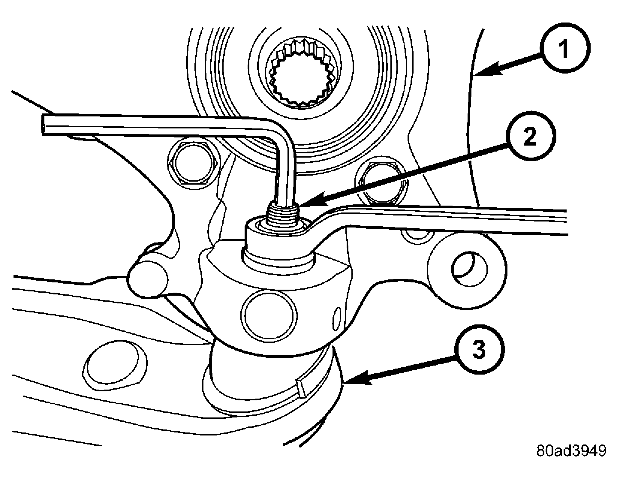 Courtesy of DAIMLERCHRYSLER CORP.
| 1 - KNUCKLE |
| 2 - BALL JOINT STUD |
| 3 - LOWER CONTROL ARM |
- Slide halfshaft stub shaft into hub and bearing assembly.
CAUTION:
The steering knuckle to strut assembly attaching bolts are serrated and must not be turned during installation. Install nuts while holding bolts stationary in steering knuckle.
CAUTION:
If vehicle being serviced is equipped with eccentric cam strut attaching bolts, eccentric cam bolt must be installed in bottom (slotted) hole on strut clevis bracket. See Fig 2.
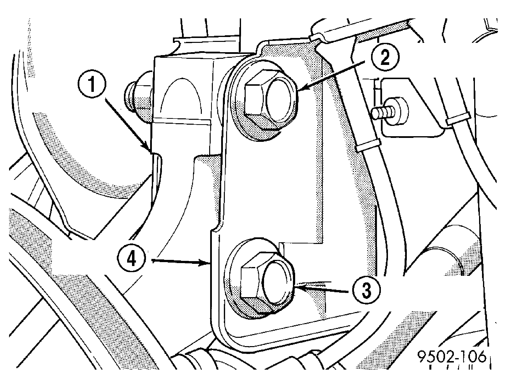 Courtesy of DAIMLERCHRYSLER CORP.
| 1 - STEERING KNUCKLE |
| 2 - FLANGED BOLT IN TOP HOLE |
| 3 - CAM BOLT IN BOTTOM HOLE |
| 4 - STRUT CLEVIS BRACKET |
NOTE:
The strut clevis-to-steering knuckle bolts are installed differently on each side. Left hand side bolts are to be installed from vehicle rear to front. See Figure. Right side bolts are to be installed from vehicle front to rear. See Figure.
- Align steering knuckle in clevis bracket of strut. Install strut clevis-to-steering knuckle attaching bolts. See Figure and Figure. Install nuts on ends of bolts and tighten to 81 N.m (60 ft. lbs.) torque. Then, tighten nuts an additional 1/4 (90°) turn after that torque is met.
CAUTION:
Before installing tie rod stud in knuckle steering arm, wipe stud and knuckle contact area free of any grease or debris, otherwise damage to knuckle can occur. Use a clean shop cloth with Mopar(R) Brake Parts Cleaner applied to it for proper cleaning. Do not spray stud directly.
- Install outer tie rod stud into knuckle steering arm from bottom. See Figure. Start nut onto tie rod stud. While holding stud stationary using a socket, tighten nut using a wrench. Using a crowfoot wrench on a torque wrench, tighten nut to 47 N.m (35 ft. lbs.) torque. Then, tighten nut an additional 1/2 (180°) turn after that torque is met.
- Place wheel speed sensor cable grommet in clip at knuckle. See Figure. Close clip.
- Attach wheel speed sensor routing bracket to strut assembly. See Figure. Tighten screw to 13 N.m (115 in. lbs.) torque.
- Clip wheel speed sensor connector and routing clip to frame rail outer reinforcement. See Figure.
- Connect vehicle wiring harness to wheel speed sensor connector. See Figure.
- Install brake rotor, then install disc brake caliper and adapter assembly. (Refer to BRAKES/HYDRAULIC/MECHANICAL/ROTOR - INSTALLATION)
- Verify that wheel speed sensor is not routed improperly allowing cable to come in contact with brake rotor or other moving parts.
- Install washer and hub nut on end of halfshaft stub shaft. See Figure. With aid of a helper applying brakes to keep front hub from turning, tighten hub nut to 244 N.m (180 ft. lbs.) torque.
- Install spring washer and hub nut lock over hub nut and stub shaft. Install a NEW cotter pin securing nut lock in place and tightly wrap cotter pin prongs around nut lock.
- Install tire and wheel assembly (Refer to TIRES/WHEELS - INSTALLATION)
. Tighten wheel mounting nuts to a torque of 135 N.m (100 ft. lbs.).
- Lower vehicle.
- Pump brake pedal several times to ensure vehicle has a firm brake pedal before moving vehicle.
- Check and adjust brake fluid level as necessary.
- Perform wheel alignment. (Refer to SUSPENSION/WHEEL ALIGNMENT - STANDARD PROCEDURE)