Fuel Injectors (Using Lab Scope)
WARNING: This page is about a different car, the 2002 Dodge Stratus and 2002 Chrysler Sebring. However, it is still accessible from the selected car via links, so may be relevant.
NOTE:
For fuel injector circuit testing, see DTCs P0201-P0204: INJECTORS NO. 1-4 CIRCUIT MALFUNCTION under DIAGNOSTIC TESTS in SELF-DIAGNOSTICS - SEBRING COUPE & STRATUS COUPE - 2.4L article. Manufacturer recommends connecting Test Connector (MB991709) to fuel injector during testing procedure.
- Connect lab scope pick-up at fuel injector connector or Engine Control Module/Powertrain Control Module (ECM/PCM) connector. If connecting lab scope pick-up at fuel injector connector, connect pick-up lead to fuel injector connector terminal No. 2 by backprobing. See FUEL INJECTOR TERMINAL IDENTIFICATION (M/T)
or FUEL INJECTOR TERMINAL IDENTIFICATION (A/T)
tables.
- If connecting lab scope pick-up at ECM (M/T), connect pick-up lead to corresponding fuel injector ECM/PCM connector by backprobing. See FUEL INJECTOR TERMINAL IDENTIFICATION (M/T)
or FUEL INJECTOR TERMINAL IDENTIFICATION (A/T)
tables.
- Start engine and let engine idle. Compare waveform to normal pattern. See Fig 1
. Waveform should be stable with engine idling. If point "A" is extremely small or does not appear, fuel injector solenoid is shorted. Point "B" should extend when engine RPM is suddenly increased. After RPM steadies, point "B" will return to normal. If point "B" is erratic, problems with the ECM/PCM exist.
FUEL INJECTOR TERMINAL IDENTIFICATION (M/T)
| Cylinder No. |
ECM Connector C-109 Terminal No. |
Wire Color |
| 1 |
1 |
Yellow/Blue |
| 2 |
14 |
Yellow/Red |
| 3 |
2 |
Yellow/Black |
| 4 |
15 |
Green/Yellow |
FUEL INJECTOR TERMINAL IDENTIFICATION (A/T)
| Cylinder No. |
PCM Connector C-110 Terminal No. |
Wire Color |
| 1 |
1 |
Yellow/Blue |
| 2 |
9 |
Yellow/Red |
| 3 |
24 |
Yellow/Black |
| 4 |
2 |
Green/Yellow |
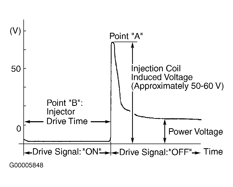 Courtesy of MITSUBISHI MOTOR SALES OF AMERICA.