Diagnostic Procedure
- Turn ignition switch to ON position. Using scan tool, actuate generator field driver circuit. Using a 12-volt test light, backprobe generator field driver terminal connector. See Fig 1
. If 12-volt test light illuminates and flashes, go to next step. If 12-volt test light does not illuminate and flash, go to step 4
.
- With generator field driver circuit actuated, wiggle harness from generator to Powertrain Control Module (PCM). Using scan tool, record DTCs. If P0622 resets, repair circuit as necessary where wiggling caused problem to appear. See WIRING DIAGRAMS
. Perform CHARGING SYSTEM VERIFICATION TEST
under VERIFICATION TESTS. If P0622 does not reset, go to next step.
- Turn ignition switch to OFF position. Inspect wiring harness and connector. See WIRING DIAGRAMS
. If fault is found, repair as necessary. Perform CHARGING SYSTEM VERIFICATION TEST
under VERIFICATION TESTS. If no fault is found, test is complete.
- Using scan tool, record all DTCs and freeze frame data. Erase DTCs. Carefully inspect all connectors for corrosion. Disconnect generator field driver harness connector. Using scan tool, actuate generator field driver circuit. Using a 12-volt test light, probe between ground and Auto Shut Down (ASD) relay circuit terminal at generator field harness connector. See WIRING DIAGRAMS
. If 12-volt test light illuminates, go to next step. If 12-volt test light does not illuminate, repair open in ASD relay circuit. Perform CHARGING SYSTEM VERIFICATION TEST
under VERIFICATION TESTS.
- Turn ignition switch to OFF position. Disconnect PCM harness connector. Measure resistance between ground and generator field driver circuit terminal at PCM harness connector. If resistance is less than 5 ohms, repair short to ground in generator field driver circuit between generator and PCM. See WIRING DIAGRAMS
. Perform CHARGING SYSTEM VERIFICATION TEST
under VERIFICATION TESTS. If resistance is 5 ohms or greater, go to next step.
- Measure resistance of generator field driver circuit between PCM harness connector and generator field driver harness connector. See WIRING DIAGRAMS
. If resistance is less than 5 ohms, go to next step. If resistance is 5 ohms or greater, repair open in generator field driver circuit between generator and PCM. Perform CHARGING SYSTEM VERIFICATION TEST
under VERIFICATION TESTS.
- Measure resistance between generator field terminals (component side) at generator. If resistance is less than 5 ohms, replace shorted generator. See GENERATOR
under REMOVAL & INSTALLATION. Perform CHARGING SYSTEM VERIFICATION TEST
under VERIFICATION TESTS. If resistance is 5 ohms or greater, replace PCM. Perform CHARGING SYSTEM VERIFICATION TEST
under VERIFICATION TESTS.
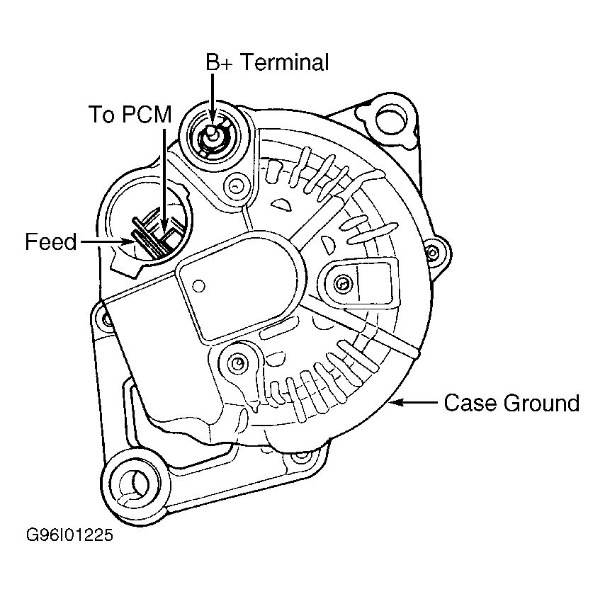 Courtesy of CHRYSLER CORP.