Courtesy Light Inoperative With Any Door (Sebring Convertible)
- Connect scan tool to DLC. DLC is located above hood release handle on driver's kick panel. Select BODY CONTROL MODULE on scan tool. If scan tool displays NO RESPONSE, go to BATTERY POWER TO MODULE DISCONNECT; IGNITION VOLTAGE TOO LOW; NO RESPONSE FROM BCM (BAT PWR DISCON'D); BATTERY POWER TO MODULE under COMMUNICATIONS. If scan tool displays CCD BUS FAILURE, go to appropriate bus failure procedure under COMMUNICATIONS . If neither message is displayed, go to next step.
- Using scan tool, actuate courtesy lights. If courtesy lights illuminate, go to next step. If courtesy lights do not illuminate, go to step 4.
- Stop courtesy light actuation. Open left front door. Using scan tool, read driver door ajar switch status. If scan tool displays DRIVER DOOR AJAR: CLOSED, replace BCM. See BODY CONTROL MODULE (BCM) under REMOVAL & INSTALLATION. If scan tool does not display DRIVER DOOR AJAR: CLOSED, go to OPEN DRIVER DOOR (LEFT FRONT) AJAR CIRCUIT; COURTESY LIGHT INOPERATIVE WITH LEFT FRONT DOOR (ALL MODELS) under DOOR AJAR.
- Stop courtesy light actuation. Remove illuminated entry relay harness connector. Relay is located above brake pedal. Using DVOM, measure voltage between ground and terminal No. 4 (Pink wire) on illuminated entry relay harness connector. See Fig 1. If voltage is greater than 10 volts, go to next step. If voltage is 10 volts or less, repair open in Pink wire between illuminated entry relay harness connector and junction block.
- Using DVOM, measure voltage between ground and terminal No. 8 (Yellow wire) on illuminated entry relay harness connector. If voltage is greater than 9 volts, go to next step. If voltage is 9 volts or less, repair open in Yellow wire.
- Using DVOM, measure resistance between ground and terminal No. 2 (Black wire) on illuminated entry relay harness connector. If resistance is less than 10 ohms, go to next step. If resistance is 10 ohms or greater, repair open in Black wire.
- Connect test light between terminals No. 4 and 6 on illuminated entry relay harness connector. Using scan tool, actuate courtesy lights. If test light does not illuminate, go to next step. If test light illuminates, replace illuminated entry relay.
- Stop courtesy light activation. Reconnect illuminated entry relay. Using DVOM, backprobe junction block 6-pin connector C10. Measure voltage between ground and junction block 6-pin connector C10 terminal No. 1 (Brown/Light Green wire). See CONNECTOR IDENTIFICATION . If voltage is greater than 9 volts, go to next step. If voltage is 9 volts or less, repair open in Brown/Light Green wire between BCM and illuminated entry relay.
- Replace BCM. See BODY CONTROL MODULE (BCM) under REMOVAL & INSTALLATION.
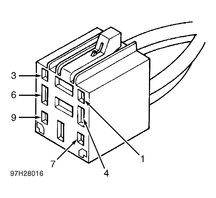 Courtesy of CHRYSLER LLC