Cruise Control Servo Test
- Turn ignition switch to ON position. Using a voltmeter, connect negative lead to a good chassis ground. Disconnect servo 4-pin connector. See Fig 1
. Measure voltage at terminal No. 2 (Dark Blue/Red wire) at servo connector. If battery voltage is not present, go to next step. If battery voltage is present, go to step 7).
- Disconnect brakelight switch 6-pin connector. Measure voltage at terminal No. 6 (Dark Blue/Red wire). If battery voltage is present, test brakelight switch. Replace brakelight switch, if defective. If brakelight switch is okay, repair Dark Blue/Red wire as necessary. See BRAKELIGHT SWITCH TEST
under TESTING (WITHOUT DRB-II). If battery voltage is not present, go to next step.
- Gain access to cruise control switch. See Fig 1
. Disconnect cruise control 4-pin connector. Measure voltage at terminal No. 1 (Yellow/Red wire) at cruise control connector.
- If battery voltage is not present, go to step 6). If battery voltage is present, test cruise control switch. See CRUISE CONTROL SWITCH TEST
. Replace cruise control switch, if defective. If cruise control switch is okay, check for continuity across clockspring. See Fig 1
.
- If no continuity exists across clockspring, replace clockspring. If continuity exists across clockspring, repair Yellow/Red wire between clockspring and brakelight switch.
- If battery voltage is not present in step 4), measure voltage at input side of cruise control fuse. If battery voltage is not present, repair open in wire between ignition switch and cruise control fuse. If battery voltage is present, check cruise control fuse. Replace fuse if blown. If fuse is okay, repair wire between fuse and clockspring.
- If battery voltage is present in step 1), connect a jumper wire between terminal No. 2 (Dark Blue/Red wire) at cruise control servo connector and terminal No. 2 at cruise control servo.
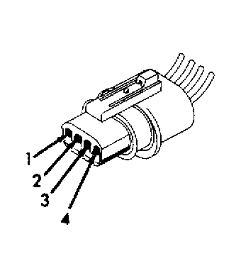 Courtesy of CHRYSLER MOTORS
- With jumper wire connected, battery voltage should be present at servo's 3 remaining terminals. If battery voltage is present at servo's 3 remaining terminals, go to next step. If battery voltage is not present at servo's 3 remaining terminals, replace servo.
- Using an ohmmeter, connect one lead to good chassis ground. Connect remaining lead to terminal No. 1 (Black wire) at servo connector. If no continuity exists, repair open in Black wire. If continuity exists, test is complete.