Terminal Removal Procedure
 Courtesy of GENERAL MOTORS COMPANY
 Courtesy of GENERAL MOTORS COMPANY
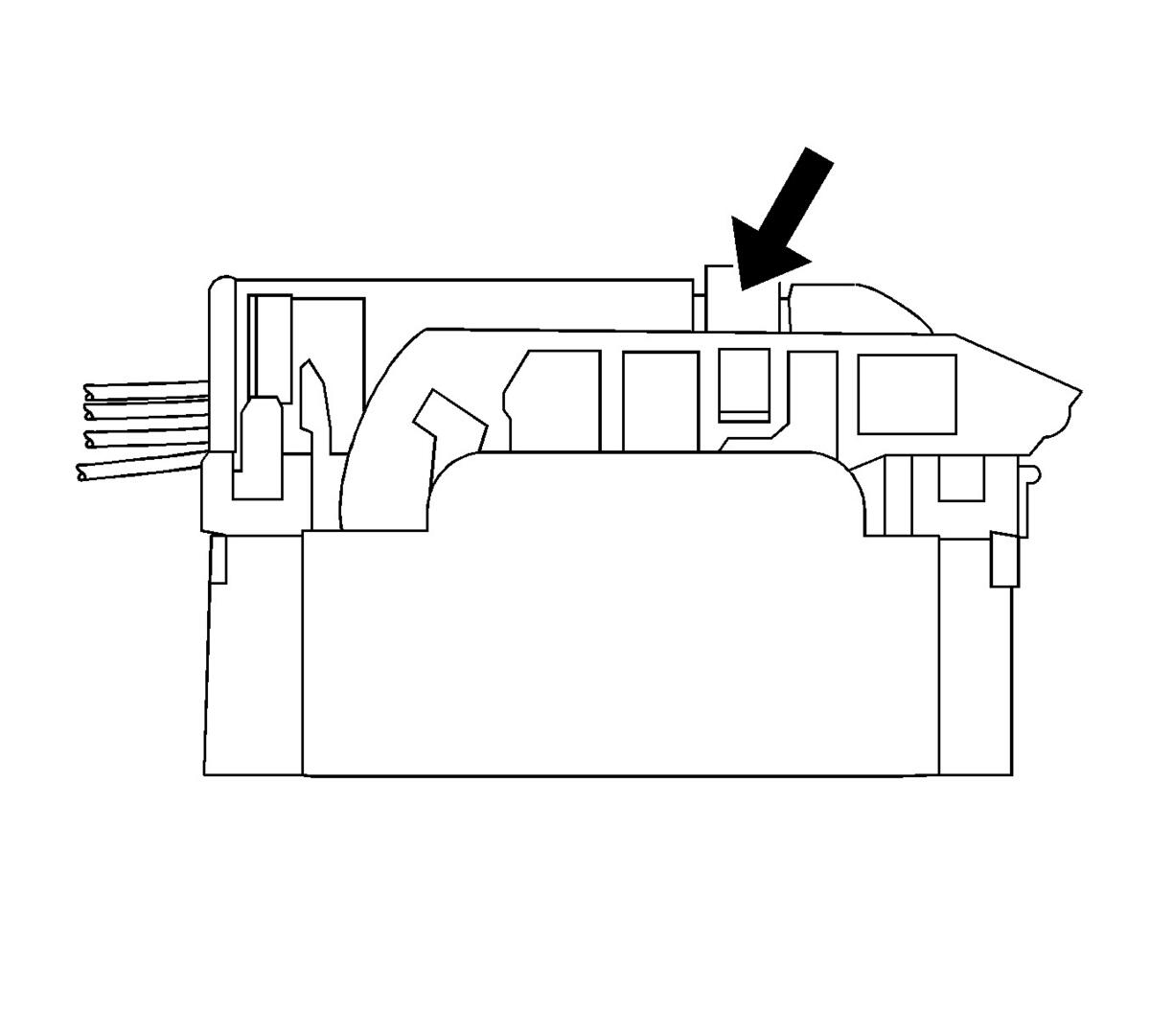
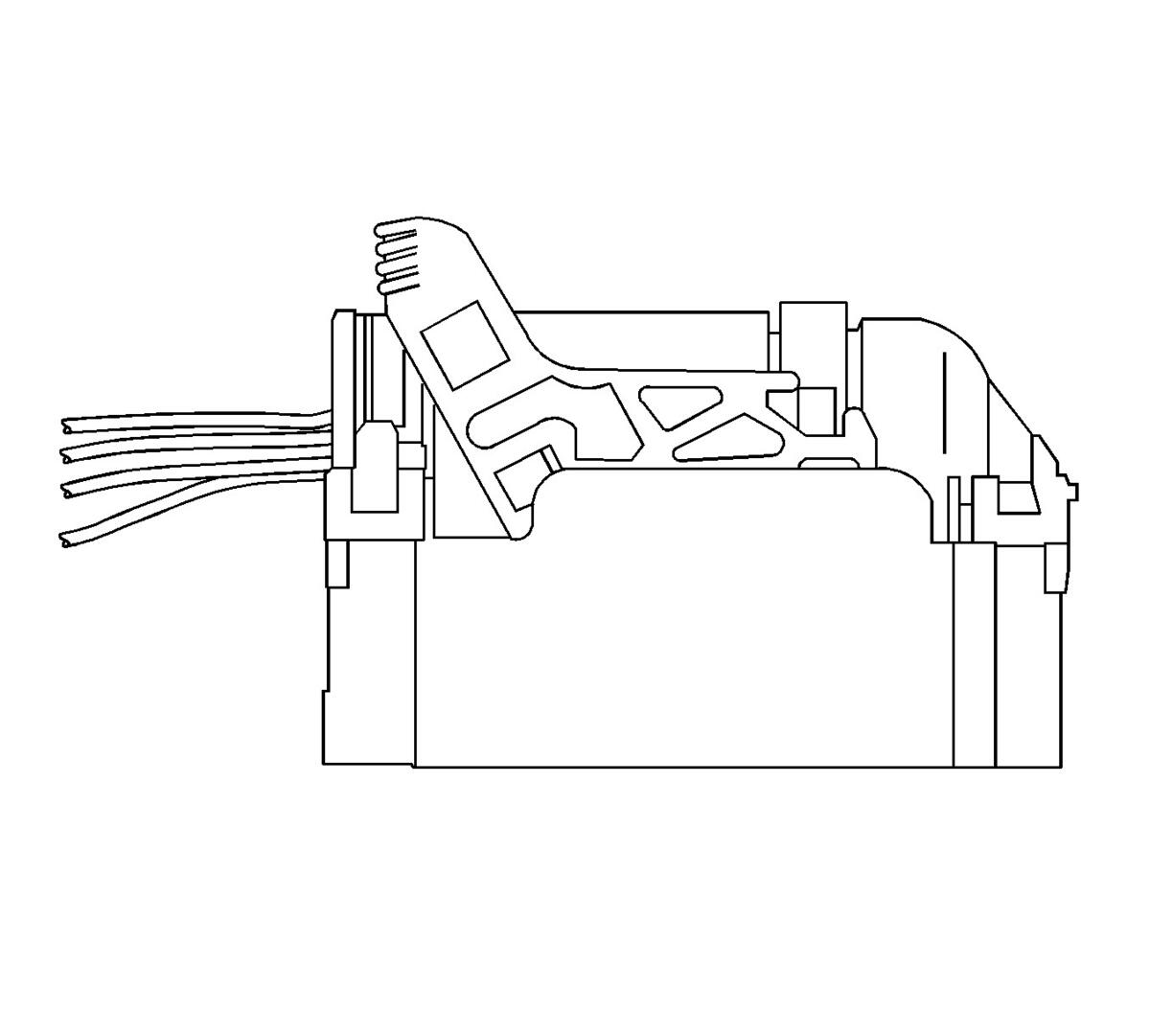
- Slide the lever lock forward while pressing down on the lever lock release tab.
- Disconnect the connector from the component.
 Courtesy of GENERAL MOTORS COMPANY
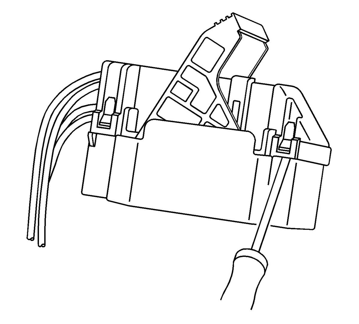
- Remove the dress cover by using a flat-blade tool to release the connector locking tabs and pulling off the dress cover.
 Courtesy of GENERAL MOTORS COMPANY
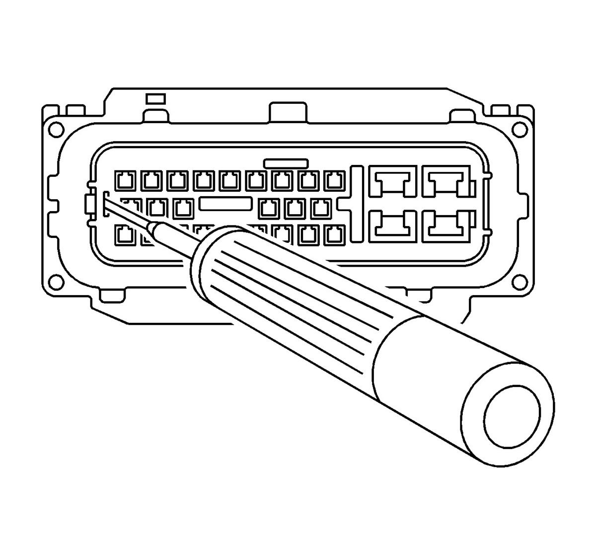
- Relieve the tension on the nose piece retainers by inserting J-38125-12A into the single retainer slot on the end of the nose piece and gently prying out the locking tab. Repeat the process for both of the nose piece locking tabs on the opposite side of the nose piece.
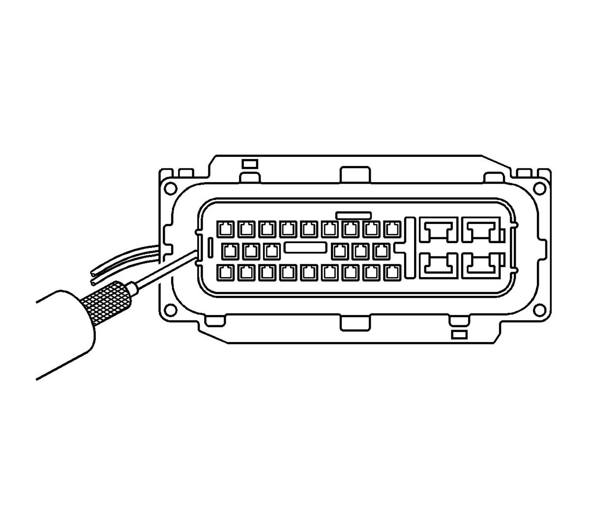 Courtesy of GENERAL MOTORS COMPANY
- Once the nose piece retainers are relaxed, use the J-38125-552 to pull up the nose piece by hooking the tool under the nose piece and pulling up. The nose piece should raise slightly.
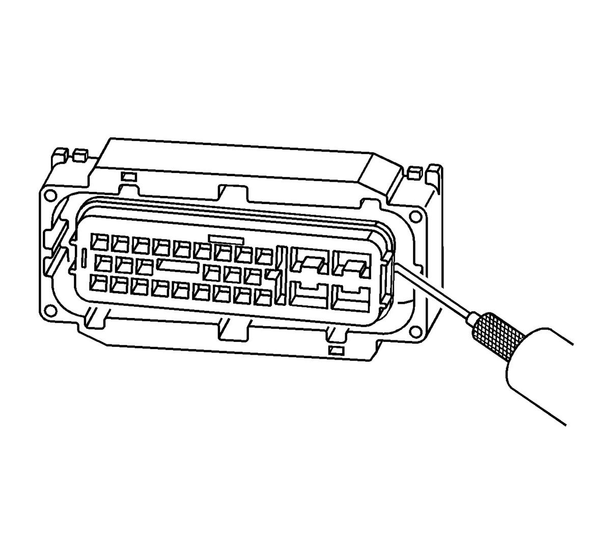 Courtesy of GENERAL MOTORS COMPANY
- On the opposite side of the nose piece, use the J-38125-552 pull up the nose piece by hooking the tool under the nose piece and pulling up. The nose piece should release completely. If the nose piece does not come off, repeat the procedure on the opposite side.
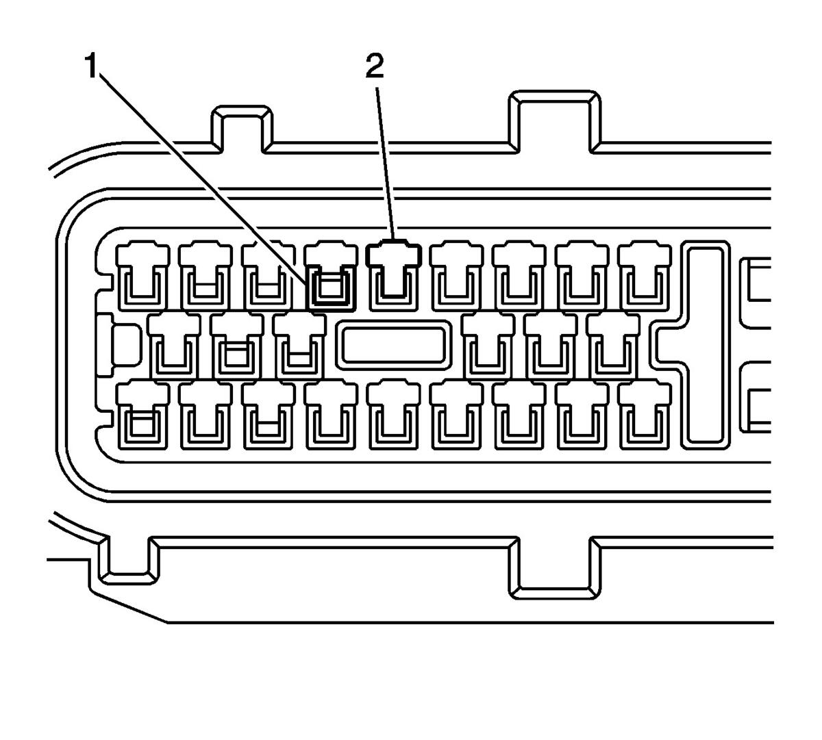 Courtesy of GENERAL MOTORS COMPANY
- The illustration above identifies the entry canal where the terminal release tool will be inserted, and the terminal cavity.
- Terminal (1)
- Entry Canal (2)
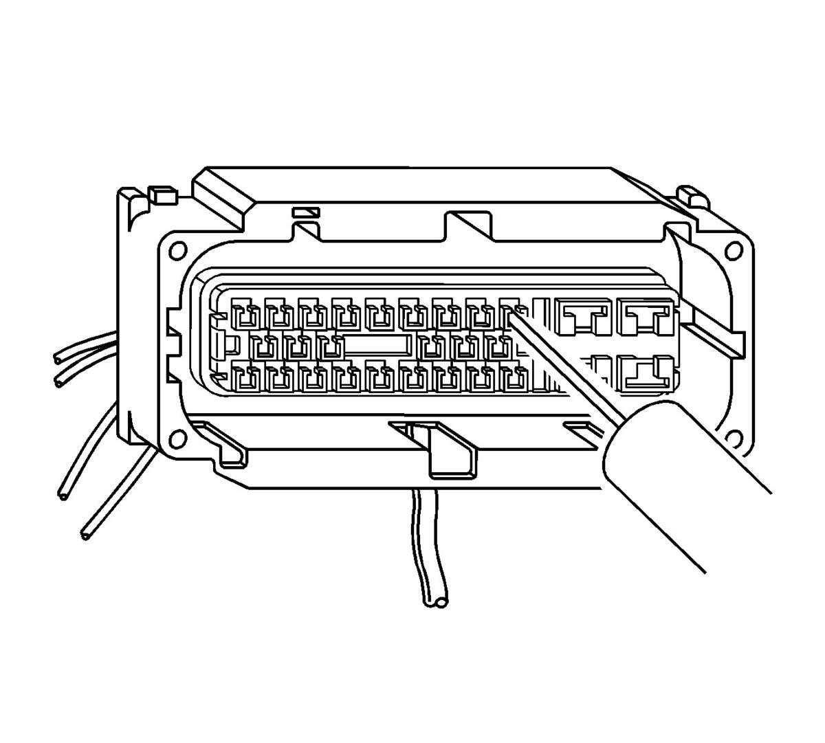 Courtesy of GENERAL MOTORS COMPANY
- Insert the J-38125-553 tool into the entry canal and pry up on the terminal retainer. The terminal retainer is a small plastic piece on the top of the terminal. The terminal retainer must be held up while the terminal is pulled out of the connector.
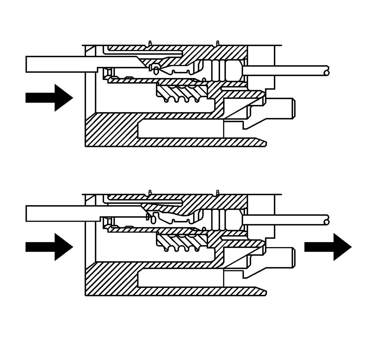 Courtesy of GENERAL MOTORS COMPANY
- The illustration shows a cutaway view of the connector to aid the technician in releasing the terminal retainer.
- Repair the terminal by following the Repairing Connector Terminals (Terminated Lead Repair) Repairing Connector Terminals (Terminal Repair) procedure.
- Insert the repaired terminal back into the cavity. Repeat the diagnostic procedure to verify the repair and reconnect the connector bodies.