- Before performing any adjustment affecting the wheel alignment, refer to Wheel Alignment Measurement .
NOTE:
Service bolt is available for the lower strut to steering knuckle position. Do not attempt to file on the strut to make camber adjustment. The service bolt is approximately 2 mm smaller in diameter to allow adjustment. Refer to the electronic parts catalog for proper application.
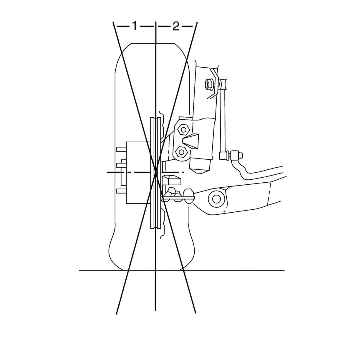
- Determine the actual camber, Positive (1) or Negative (2).
 Courtesy of GENERAL MOTORS COMPANY
- Raise the front of the vehicle. Follow alignment machine instructions.
- Remove the tire and wheel assembly. Follow alignment machine instructions.
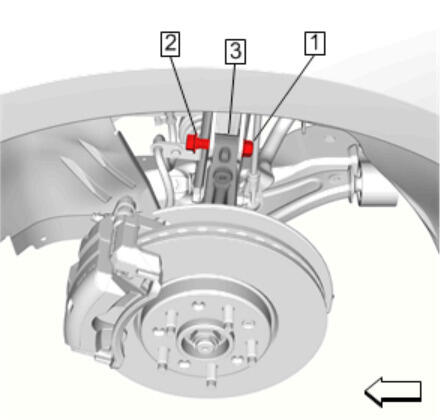
- Loosen the upper steering knuckle nut (1) enough to allow the splines of the steering knuckle bolt (2) to disengage from the steering knuckle (3). Refer to Strut Assembly Removal and Installation
 Courtesy of GENERAL MOTORS COMPANY
- Remove the lower steering knuckle nut and bolt and DISCARD the bolt.
- Install service bolt to lower strut to steering knuckle. Do not fully tighten.
- Install the tire and wheel assembly.
- Adjust the front camber to specifications. Refer to Wheel Alignment Measurement
NOTE:
For accurate readings, do not push or pull on the tire and wheel assembly during the alignment.
NOTE:
The next step may require assistance.
 Courtesy of GENERAL MOTORS COMPANY
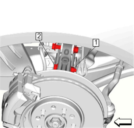
- Hold the camber adjustment and tighten the bottom steering knuckle nut (1) while holding the steering knuckle bolt (2) to secure the adjustment. Do not fully torque at this time. Also make sure that the spline of the bolt is fully seated within the knuckle and strut.
- Lower the front wheels. Follow alignment machine instructions.
- Re-inspect the camber settings.
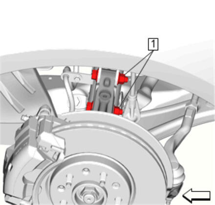
- Steering Knuckle Nut (1) [2x]» Tighten - Strut Assembly Removal and Installation
 Courtesy of GENERAL MOTORS COMPANY
- Adjust the front toe. Refer to Wheel Alignment - Steering Wheel Angle and/or Front Toe Adjustment
NOTE:
After adjusting the front camber, it is necessary to adjust the front toe.