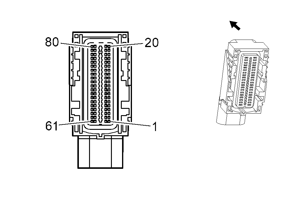
K20 Engine Control Module X2
 Courtesy of GENERAL MOTORS CORP.
 K20 Engine Control Module X2
| Pin |
Size |
Color |
Circuit |
Function |
Option |
| 1 |
0.5 |
- |
- |
Not Used |
- |
| 2 |
0.5 |
L-GN |
1867 |
5-Volt Reference |
- |
| 3 |
0.5 |
GY |
2701 |
5-Volt Reference |
- |
| 4 |
- |
- |
- |
Not Used |
- |
| 5 |
0.75 |
BN |
582 |
TAC Motor Control - 2 |
- |
| 6 |
0.75 |
YE |
581 |
TAC Motor Control - 1 |
- |
| 7 |
- |
- |
- |
Not Used |
- |
| 8 |
0.75 |
D-GN/WH |
428 |
EVAP Canister Purge Solenoid Control |
- |
| 9 |
0.75 |
GY |
5493 |
Cylinder Shutoff Solenoid Control 3 |
- |
| 10 |
0.75 |
D-BU |
5491 |
Cylinder Shutoff Solenoid Control 1 |
- |
| 11 |
0.75 |
OG |
5494 |
Cylinder Shutoff Solenoid Control 4 |
- |
| 12 |
0.5 |
GY/WH |
3113 |
HO2S Heater Low Control (Bank 1 Sensor 1) |
- |
| 13 |
0.5 |
L-GN |
3212 |
HO2S Heater Low Control (Bank 2 Sensor 1) |
- |
| 14 |
0.75 |
L-GN |
5492 |
Cylinder Shutoff Solenoid Control 2 |
- |
| 15-16 |
- |
- |
- |
Not Used |
- |
| 17 |
0.75 |
D-BU/WH |
878 |
Fuel Injector 8 Control |
- |
| 18 |
0.75 |
BN/WH |
845 |
Fuel Injector 5 Control |
- |
| 19 |
0.75 |
YE/BK |
846 |
Fuel Injector 6 Control |
- |
| 20 |
0.75 |
BN/BK |
1744 |
Fuel Injector 1 Control |
- |
| 21 |
0.5 |
YE/D-GN |
410 |
ECT Sensor Signal |
- |
| 22 |
0.5 |
BN/WH |
2761 |
Low Reference |
- |
| 23 |
0.5 |
D-GN/YE |
357 |
Oil Temperature Sensor Signal |
- |
| 24 |
0.5 |
BN/RD |
470 |
Low Reference |
- |
| 25 |
- |
- |
- |
Not Used |
- |
| 26 |
0.5 |
D-BU |
496 |
Knock Sensor 1 Signal |
- |
| 27 |
0.5 |
GY |
1716 |
Low Reference Knock Sensor Signal Return |
- |
| 28 |
- |
- |
- |
Not Used |
- |
| 29 |
0.5 |
L-BU |
1876 |
Knock Sensor 2 Signal |
- |
| 30 |
0.5 |
BN |
407 |
Low Reference |
- |
| 31 |
- |
- |
- |
Not Used |
- |
| 32 |
0.5 |
PU/WH |
23 |
Generator Field Duty Cycle Signal |
- |
| 33 |
0.5 |
BN |
1174 |
Oil Level Switch Signal |
- |
| 34 |
0.5 |
BK |
2755 |
Low Reference |
- |
| 35 |
0.5 |
BN/BK |
2752 |
Low Reference |
- |
| 36 |
- |
- |
- |
Not Used |
- |
| 37 |
0.75 |
L-GN/BK |
1745 |
Fuel Injector 2 Control |
- |
| 38 |
0.75 |
PK/BK |
1746 |
Fuel Injector 3 Control |
- |
| 39 |
0.75 |
L-BU/BK |
844 |
Fuel Injector 4 Control |
- |
| 40 |
0.75 |
OG/BK |
877 |
Fuel Injector 7 Control |
- |
| 41 |
0.5 |
GY |
2705 |
5-Volt Reference |
- |
| 42 |
- |
- |
- |
Not Used |
- |
| 43 |
0.5 |
GY |
2704 |
5-Volt Reference |
- |
| 44 |
0.5 |
OG |
631 |
5-Volt Reference |
- |
| 45-49 |
- |
- |
- |
Not Used |
- |
| 50 |
0.5 |
BN/WH |
331 |
Oil Pressure Sensor Signal |
- |
| 51-52 |
- |
- |
- |
Not Used |
- |
| 53 |
0.5 |
OG/BK |
469 |
Low Reference |
- |
| 54-55 |
- |
- |
- |
Not Used |
- |
| 56 |
0.5 |
BN/YE |
1664 |
HO2S Low Signal (Bank 1 Sensor 1) |
- |
| 57 |
0.5 |
PU/WH |
1665 |
HO2S High Signal (Bank 1 Sensor 1) |
- |
| 58 |
0.5 |
L-GN |
432 |
MAP Sensor Signal |
- |
| 59 |
0.5 |
PU |
1666 |
HO2S High Signal (Bank 2 Sensor 1) |
- |
| 60 |
0.5 |
BN/RD |
1667 |
HO2S Low Signal (Bank 2 Sensor 1) |
- |
| 61 |
0.5 |
OG/WH |
225 |
Generator Turn On Signal |
- |
| 62 |
- |
- |
- |
Not Used |
- |
| 63 |
0.5 |
PU |
486 |
TP Sensor 2 Signal |
- |
| 64 |
0.5 |
BN/WH |
633 |
CMP Sensor Signal |
- |
| 65 |
0.5 |
D-GN |
485 |
TP Sensor 1 Signal |
- |
| 66 |
0.5 |
PK/BK |
632 |
Low Reference |
- |
| 67 |
- |
- |
- |
Not Used |
- |
| 68 |
0.5 |
D-BU/WH |
1869 |
CKP Sensor Signal |
- |
| 69 |
0.5 |
YE/BK |
1868 |
Low Reference |
- |
| 70 |
0.5 |
PU |
2121 |
IC 1 Control |
- |
| 71 |
0.5 |
PU/WH |
2128 |
IC 8 Control |
- |
| 72 |
0.5 |
OG |
2127 |
IC 7 Control |
- |
| 73 |
0.5 |
OG/WH |
2122 |
IC 2 Control |
- |
| 74 |
0.5 |
L-BU/WH |
2126 |
IC 6 Control |
- |
| 75 |
0.5 |
D-GN/RD |
2125 |
IC 5 Control |
- |
| 76 |
0.5 |
D-GN/WH |
2124 |
IC 4 Control |
- |
| 77 |
0.5 |
L-BU |
2123 |
IC 3 Control |
- |
| 78 |
0.5 |
BN |
2129 |
Low Reference |
- |
| 79 |
0.5 |
BN/WH |
2130 |
Low Reference |
- |
| 80 |
- |
- |
- |
Not Used |
- |
Connector Part Information
- Harness Type: Engine
- OEM Connector: 7287-3540-40
- Service Connector: 13579715
- Description: 80-Way F
|
Terminal Part Information
- Terminated Lead: Pending
- Release Tool: J-38125-213
- Diagnostic Test Probe: J-35616-64B (L-BU)
|