Disassembly Procedure
 Courtesy of GENERAL MOTORS CORP.
- Remove the generator. Refer to Generator Replacement (2.0L) .
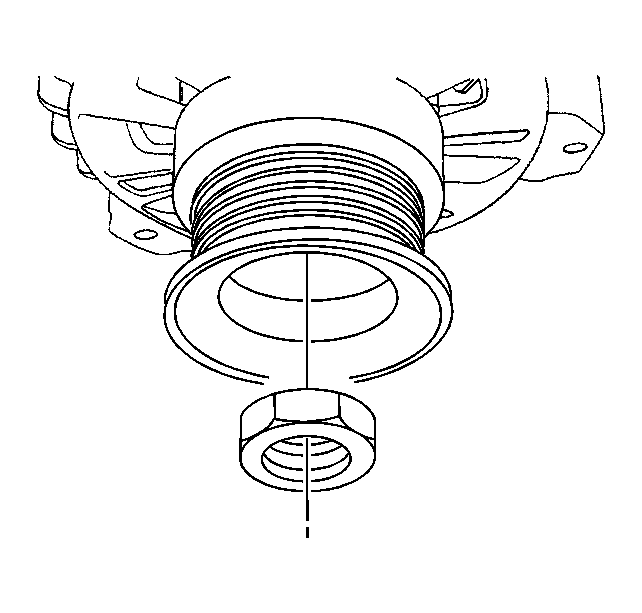
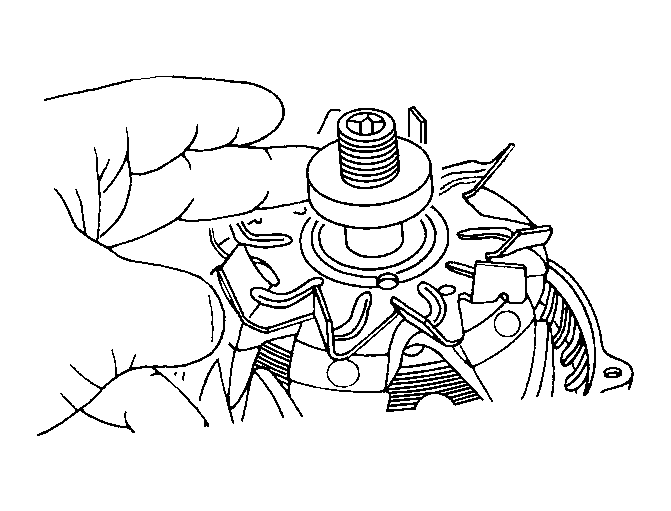
- Remove the driveshaft nut.
 Courtesy of GENERAL MOTORS CORP.
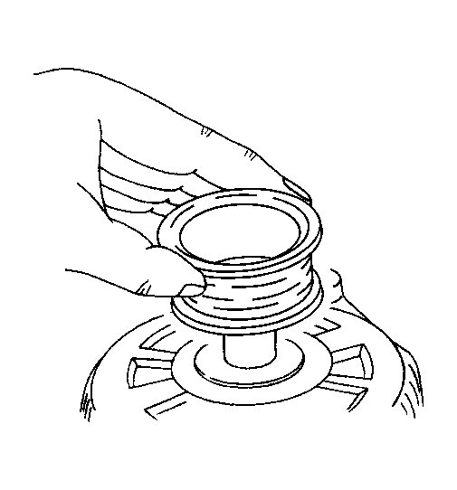
- Remove the pulley and the collar from the driveshaft.
 Courtesy of GENERAL MOTORS CORP.
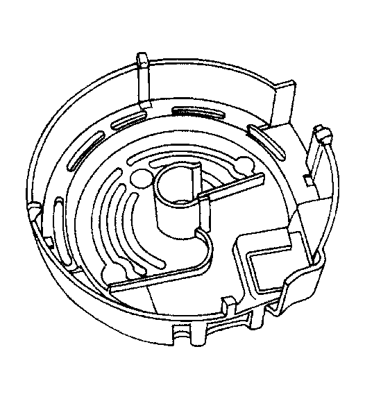
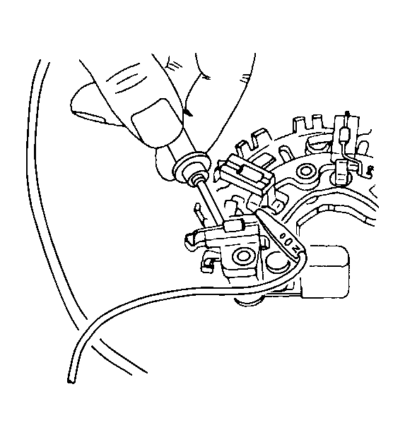
- Pry off the plastic cover that encloses the rectifier and the regulator/brush holder assemblies. Inspect the cover for damage.
 Courtesy of GENERAL MOTORS CORP.
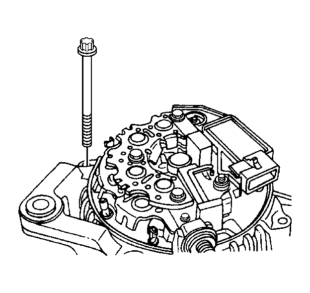
- Remove the generator through-bolts.
 Courtesy of GENERAL MOTORS CORP.
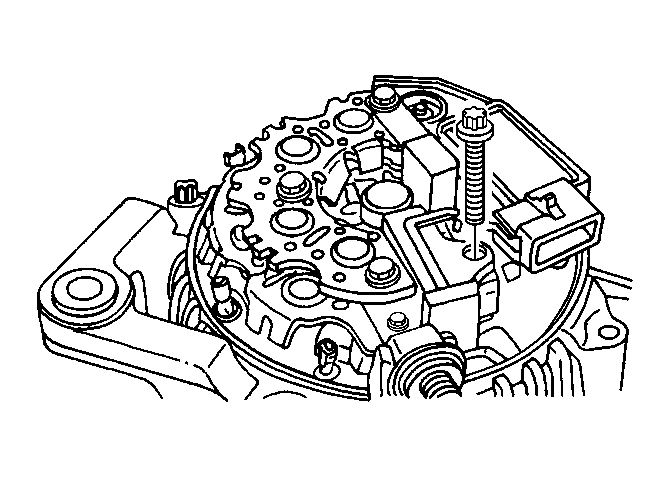
- Remove the bolts that fasten the rectifier assembly and the regulator/brush holder assembly to the slip ring end frame.
 Courtesy of GENERAL MOTORS CORP.
- To remove the regulator/brush holder and the rectifier assemblies, first melt the solder of the lead connecting the regulator/brush holder assembly to the rectifier assembly lead to the stator. Do the same to the other rectifier assembly leads to the stator, as shown.
 Courtesy of GENERAL MOTORS CORP.
- Test each of the three diodes of the rectifier assembly for continuity. Connect the ohmmeter probes on each side of the diode. Retest by connecting the ohmmeter probes reversely. If the readings are the same, replace the rectifier.
 Courtesy of GENERAL MOTORS CORP.
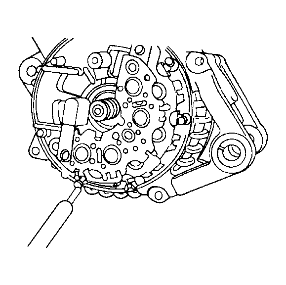
- Mark a line perpendicular to the crack between the case of the drive end frame and that of the slip ring end frame.
- Pry open the drive end frame from the slip ring end frame.
- Remove the collar.
 Courtesy of GENERAL MOTORS CORP.
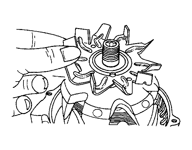
- Remove the fan.
 Courtesy of GENERAL MOTORS CORP.
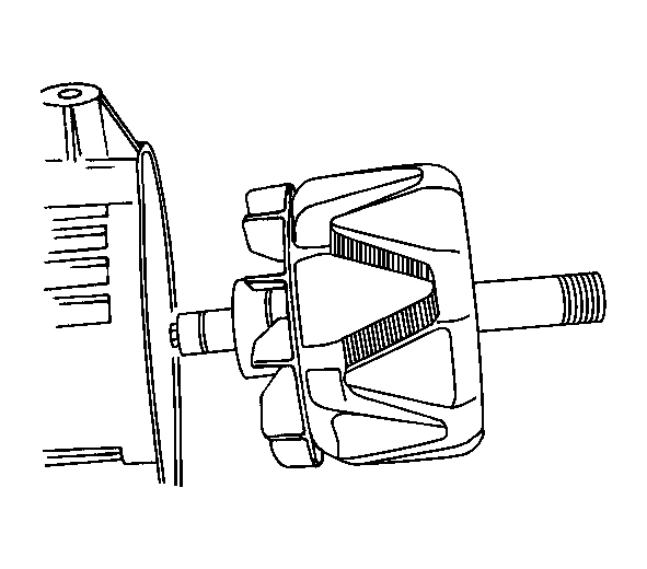
- Separate the rotor from the slip ring end frame.
 Courtesy of GENERAL MOTORS CORP.
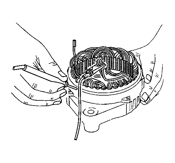
- Using the ohmmeter, test the stator for ground. If the reading is low, replace the stator. Also check the stator for an open circuit by placing the probes on two terminals. If the reading is high (infinite), replace the stator.
 Courtesy of GENERAL MOTORS CORP.
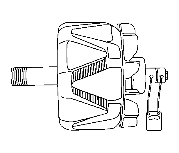
- Using an ohmmeter, test the rotor for an open circuit. Check that there is continuity between the slip rings. Standard resistance (cold) is 2.8-3.0 ohms. If there is no continuity, replace the rotor.
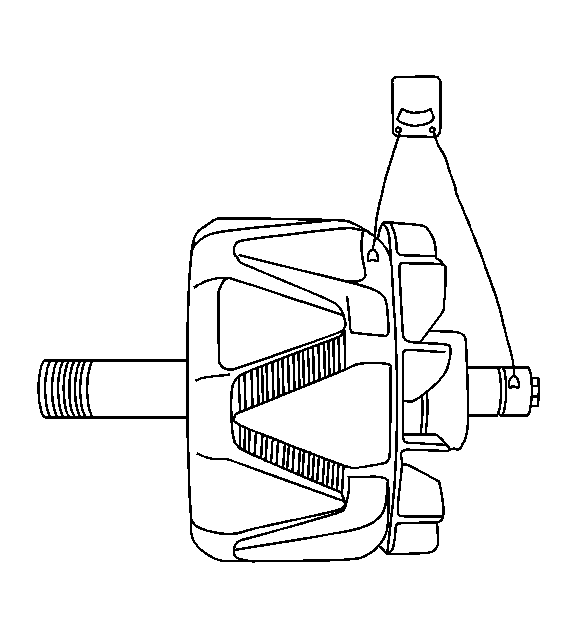 Courtesy of GENERAL MOTORS CORP.
- Using an ohmmeter, inspect the rotor for ground. Check that there is no continuity between the rotor and the slip ring.