Removal Procedure
- Raise the vehicle. Refer to Lifting and Jacking the Vehicle
in General Information.
- Remove the tire and wheel. Refer to Tire and Wheel Removal and Installation
in Tires and Wheels.
- Remove the torsion bar. Refer to Torsion Bar Replacement .
- Remove the stabilizer shaft link. Refer to Stabilizer Shaft Link Replacement (RWD) or Stabilizer Shaft Link Replacement (AWD) .
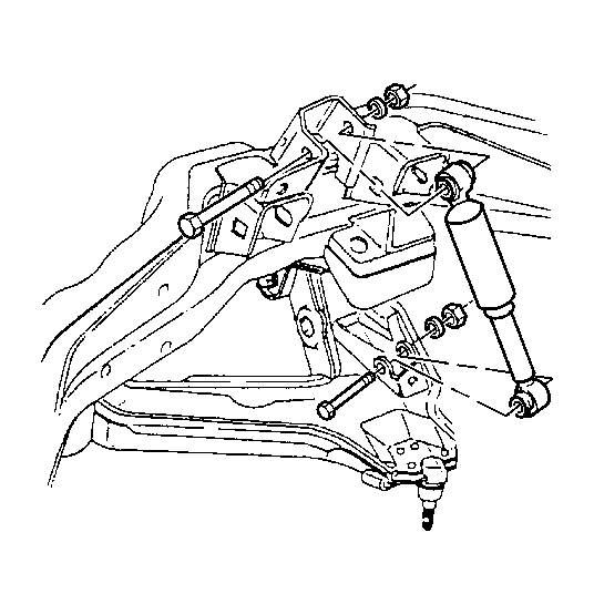
- Remove the shock absorber lower mounting bolt.
 Courtesy of GENERAL MOTORS CORP.
- Compress the shock absorber.
- Remove the rotor. Refer to Brake Rotor Replacement - Front
in Disc Brakes.
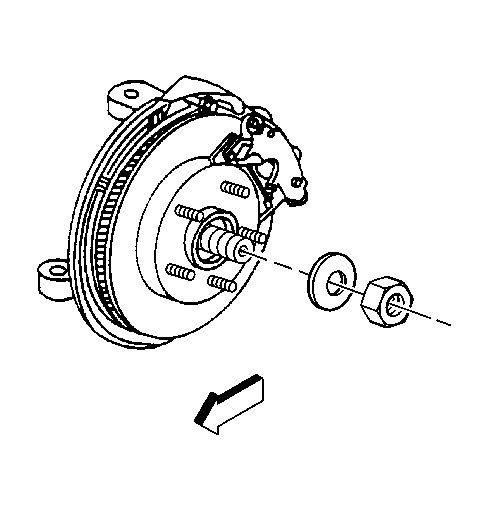
- Remove the wheel drive shaft retaining nut and the washer from the wheel hub and bearing.
 Courtesy of GENERAL MOTORS CORP.
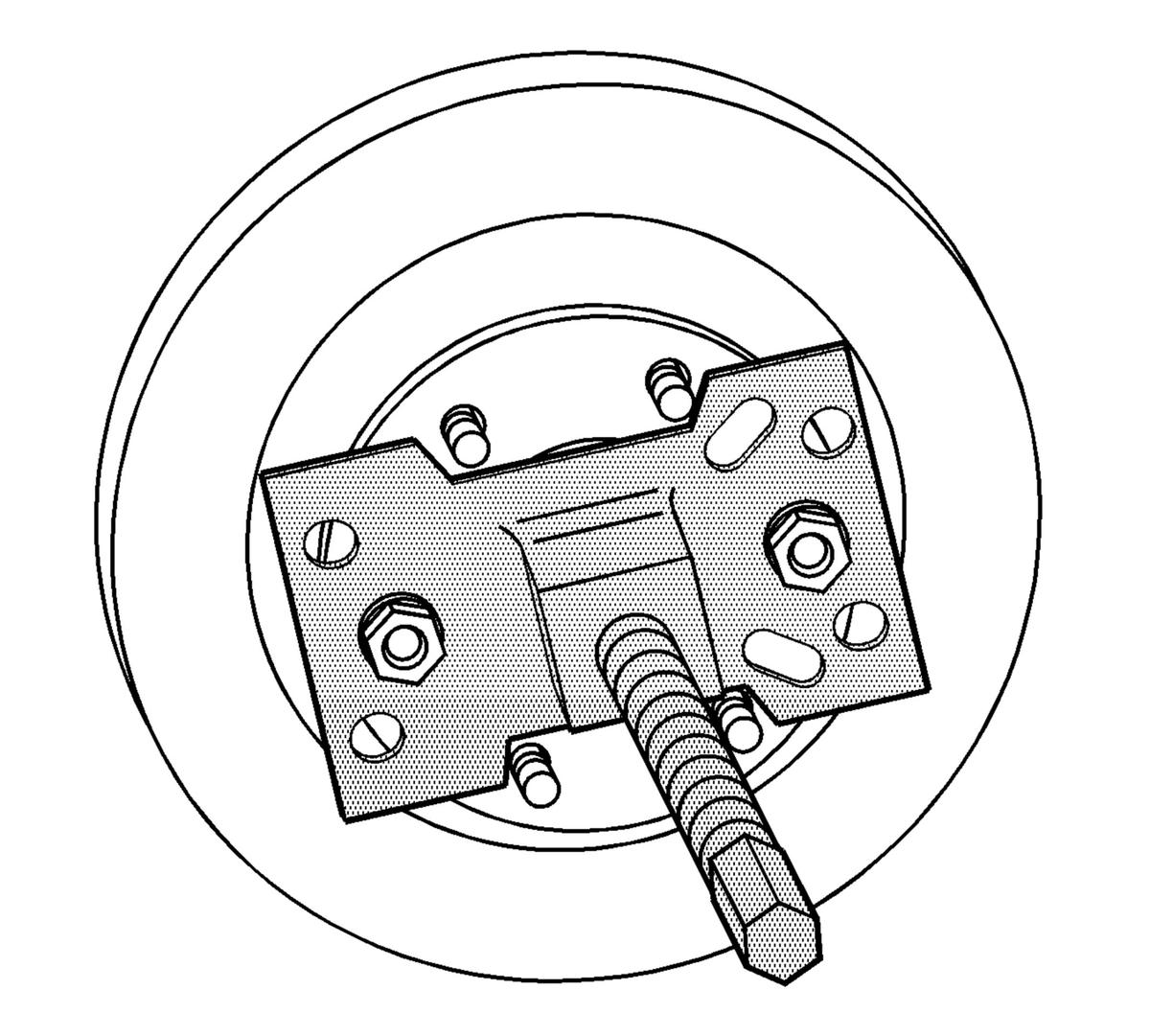
- Disengage the wheel drive shaft from the wheel hub and bearing using J 45859
.
 Courtesy of GENERAL MOTORS CORP.
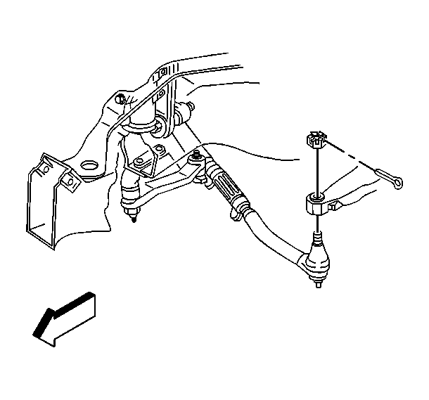
- Remove the outer tie rod cotter pin and retaining nut.
 Courtesy of GENERAL MOTORS CORP.
- Remove the outer tie rod from the steering knuckle using the J 24319-B
.
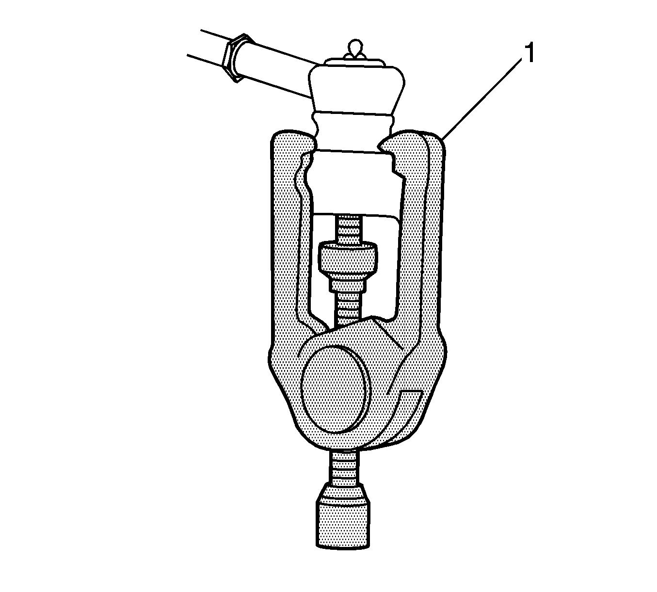 Courtesy of GENERAL MOTORS CORP.
- Disconnect the wheel speed sensor electrical connector.
- Remove the wheel speed sensor bracket retaining bolts at the frame and upper control arm.
- Disconnect the wheel speed sensor wiring harness clips form the upper control arm.
- Remove the upper ball joint cotter pin and retaining nut.
- Install the J 36607
to the upper control arm and steering knuckle.
- Disconnect the upper control arm from the steering knuckle using the J 36607
.
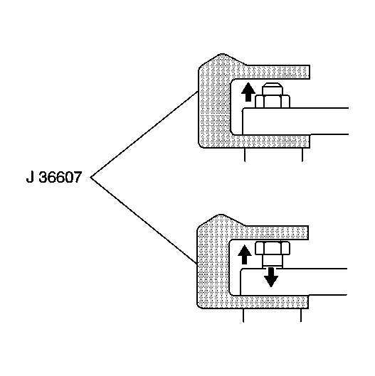 Courtesy of GENERAL MOTORS CORP.
- Remove the lower ball joint cotter pin and retaining nut.
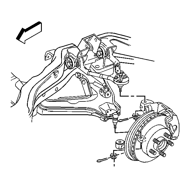 Courtesy of GENERAL MOTORS CORP.
- Using a pry bar, placed on top of the upper control arm and on the bottom of the frame, pry downward.
- With the aid of a helper, carefully hammer on the steering knuckle in the area of the lower ball joint stud in order to release the stud from the steering knuckle.
- Remove the steering knuckle and wheel hub and bearing.
- Remove the lower control arm mounting nuts and the washer.
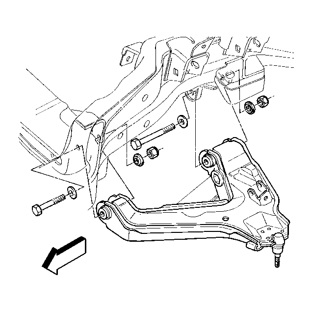 Courtesy of GENERAL MOTORS CORP.
- Remove the lower control arm mounting bolts.
- Remove the lower control arm from the vehicle.
- Remove the lower control arm brace from the lower control arm.