Removal Procedure
- Raise and support the vehicle. Refer to LIFTING AND JACKING THE VEHICLE
in General Information.
- Remove the tire and wheel assembly. Refer to TIRE & WHEEL REMOVAL & INSTALLATION
in Tires and Wheels.
- Using the J 33432-A
, remove the front transverse spring. Refer to Front Transverse Spring Replacement
.
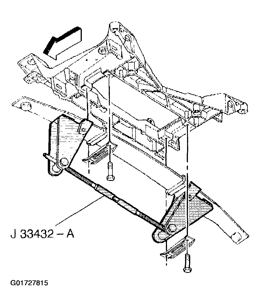 Courtesy of GENERAL MOTORS CORP.
- Disconnect the electrical connector from the wheel speed sensor.
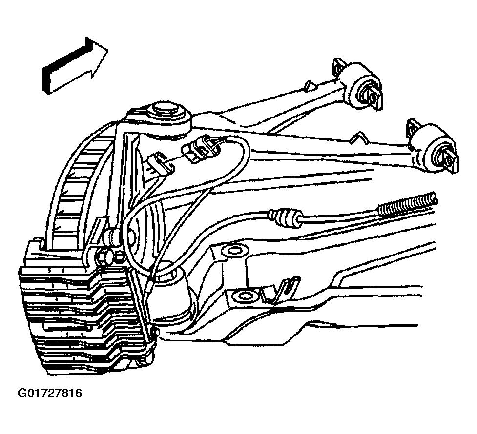 Courtesy of GENERAL MOTORS CORP.
- Disconnect the real time damping electrical connector from the shock, if equipped.
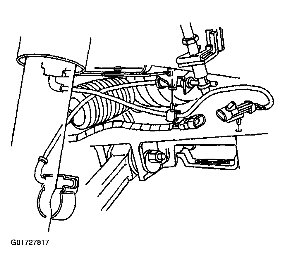 Courtesy of GENERAL MOTORS CORP.
- Remove the shock absorber from the lower control arm.
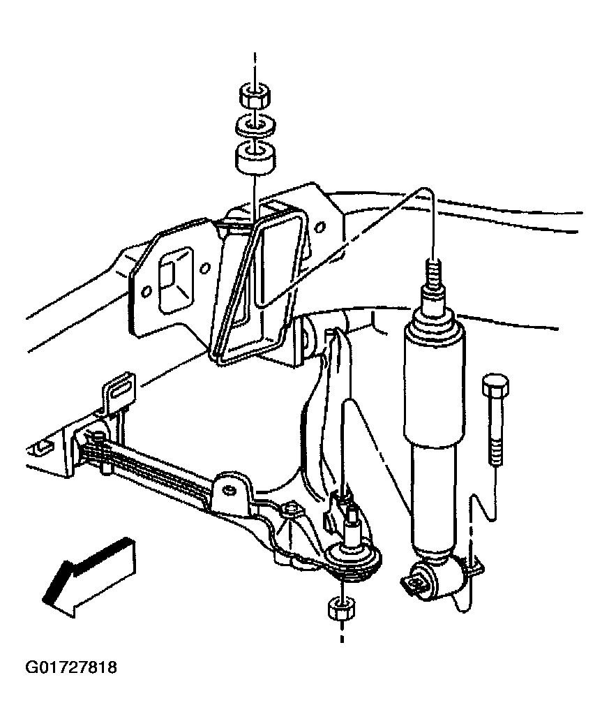 Courtesy of GENERAL MOTORS CORP.
- Remove the stabilizer shaft link from the lower control arm.
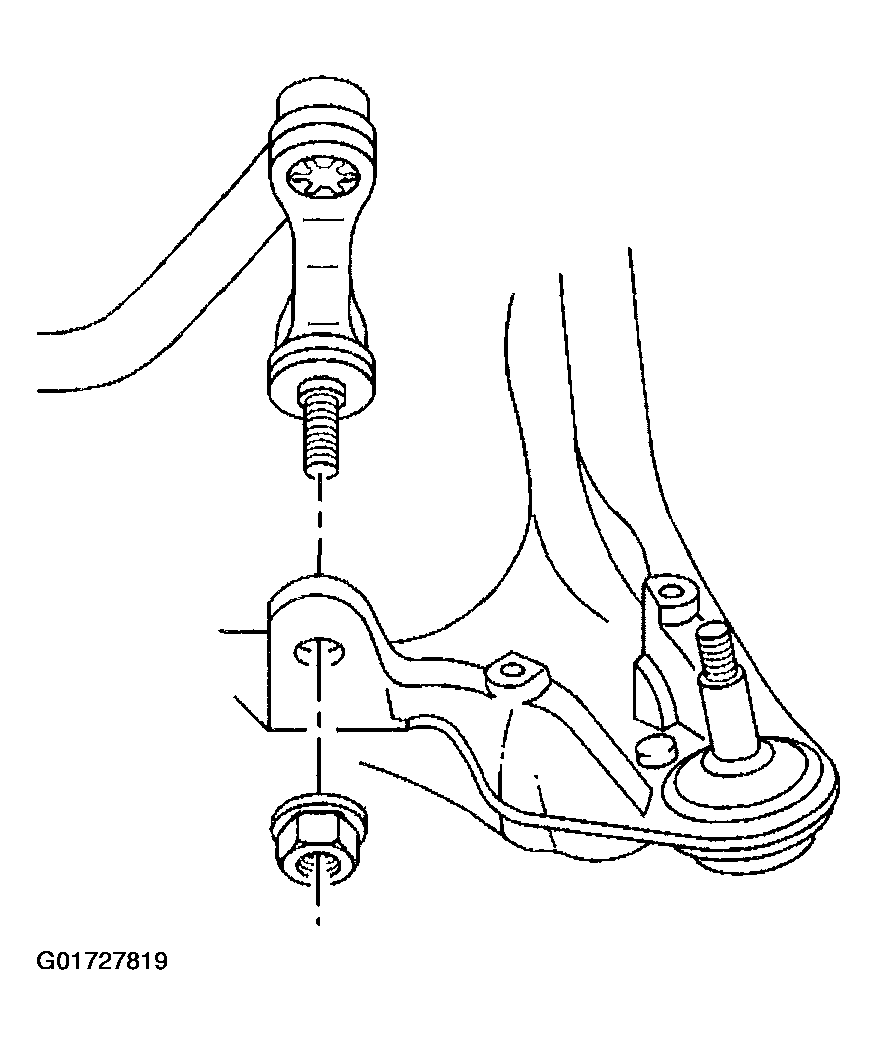 Courtesy of GENERAL MOTORS CORP.
- Loosen the ball joint stud nut but do not remove the nut.
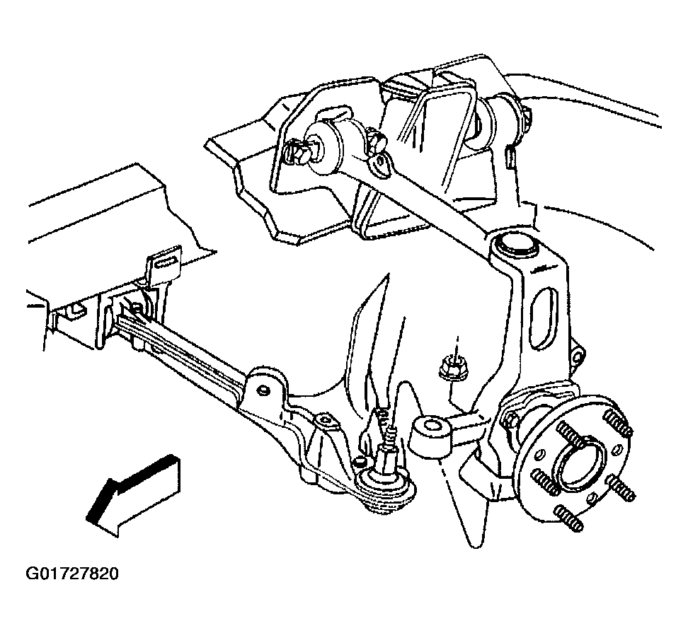 Courtesy of GENERAL MOTORS CORP.
- Using J 42188
separate the lower ball joint stud from the steering knuckle.
- Remove J 42188
and the ball joint stud nut (2).
- Remove the ball joint stud from the steering knuckle.
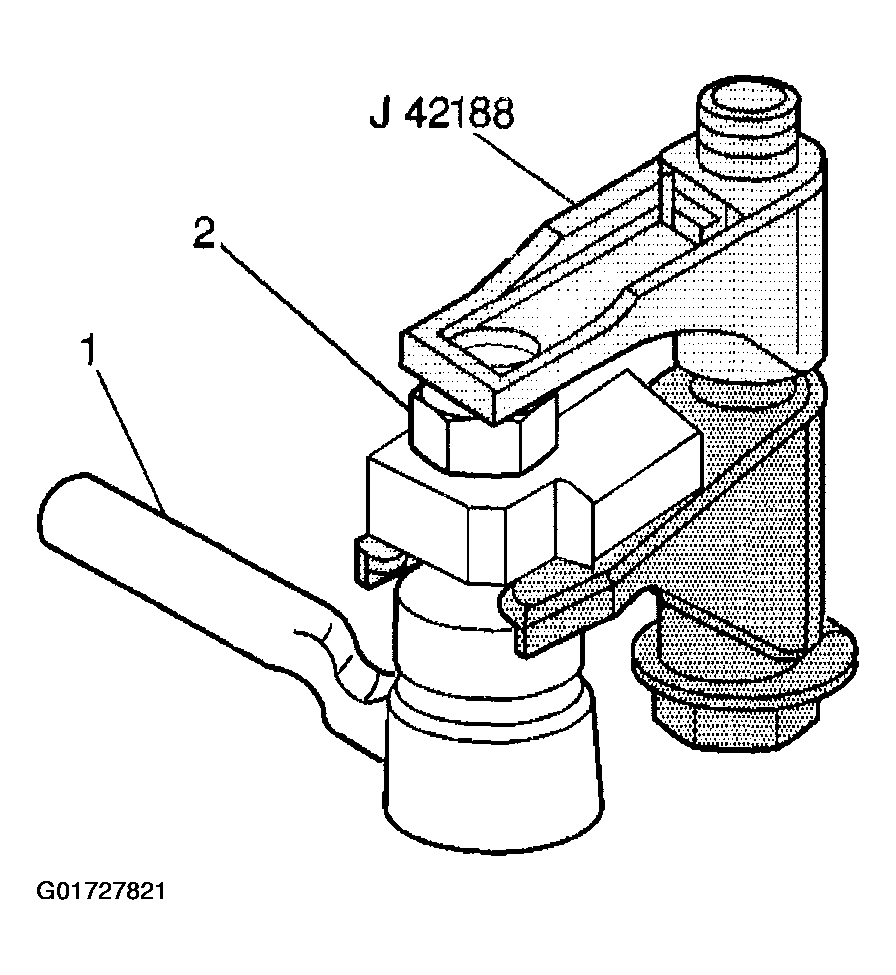 Courtesy of GENERAL MOTORS CORP.
- Mark the position of the cam bolts for orientation when installing.
- Remove the cam bolts, washers, and nuts retaining the control arm to the crossmember.
- Remove the lower control arm from the vehicle.
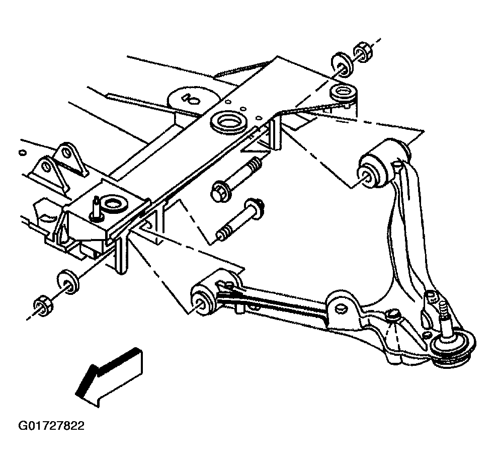 Courtesy of GENERAL MOTORS CORP.