DTC B2947: Security System Sensor Power Circuit Low: Testing
- If theft deterrent system diagnostic system check has been performed, go to next step. If theft deterrent system diagnostic system check has not been performed, perform THEFT DETERRENT SYSTEM DIAGNOSTIC SYSTEM CHECK
under SELF-DIAGNOSTIC SYSTEM.
- Connect scan tool to Data Link Connector (DLC). See Figure
. DLC is located under left side of instrument panel. Turn ignition switch to ON position. Using scan tool, select BCM DISPLAY DTCS. If scan tool displays DTC B2947 as current, go to next step. If scan tool does not display DTC B2947 as current, go to DIAGNOSTIC AIDS
.
- Disconnect Black 3-pin Passlock(R) lock cylinder harness connector. Passlock(R) lock cylinder is located to right of instrument cluster on instrument panel. It may be necessary to remove instrument cluster for access to Passlock(R) lock cylinder harness connector. See INSTRUMENT CLUSTER
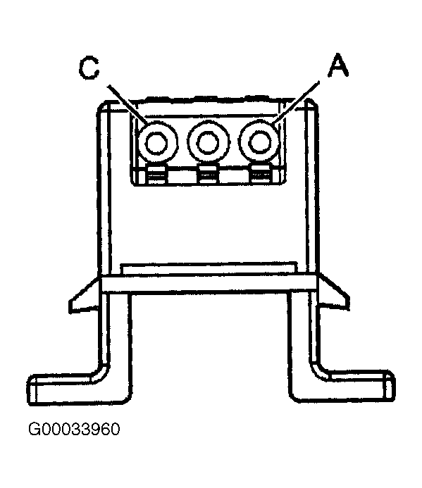
under REMOVAL & INSTALLATION. Measure voltage between ground and Passlock(R) lock cylinder harness connector terminal "C" (White wire). See Fig 1
. If battery voltage does not exist, go to next step. If battery voltage exists, go to step 7
.
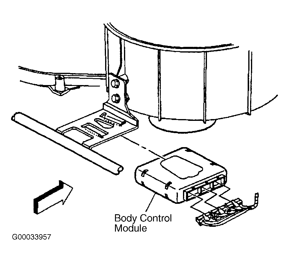
- Disconnect Pink 24-pin Body Control Module (BCM) harness connector C3. BCM is located under right side of instrument panel. See Fig 2
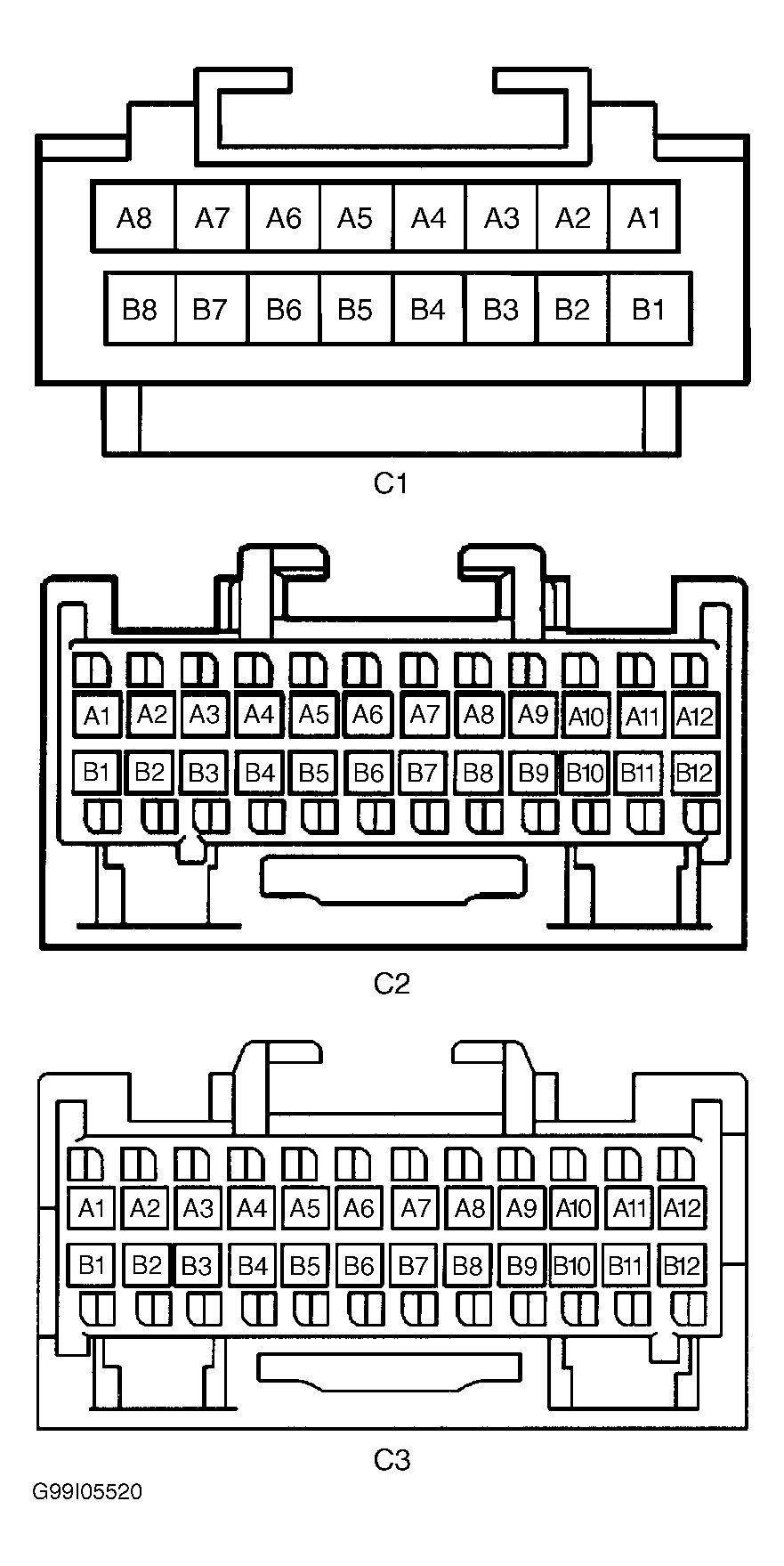
. Check for short to ground in White wire between Passlock(R) lock cylinder harness connector terminal "C" and BCM harness connector C3 terminal B4. See Fig 1
and Fig 3
. If problem does not exist, go to next step. If problem exists, repair as necessary. After repair, go to step 9
.
- Check BCM harness connectors for poor connections or damaged terminals. If problem does not exist, go to next step. If a problem exists, repair as necessary. After repair, go to step 9
.
- Check Passlock(R) lock cylinder harness connector for poor connections or damaged terminals. If problem does not exist, go to step 8
. If a problem exists, repair as necessary. After repair, go to step 9
.
- Replace and program BCM. BCM is located under right side of instrument panel. See Fig 2
. See BODY CONTROL MODULE
under REMOVAL & INSTALLATION. After repair, go to step 9
.
- Replace Passlock(R) lock cylinder. See PASSLOCK(R) LOCK CYLINDER
under REMOVAL & INSTALLATION. Perform reprogramming procedure. See THEFT DETERRENT SYSTEM
under PROGRAMMING.
- Reconnect all disconnected components and connectors. Clear DTCs. Operate vehicle under conditions that set DTC. If DTC resets, go to step 3
. If DTC does not reset, system is okay.
 Courtesy of GENERAL MOTORS CORP.
 Courtesy of GENERAL MOTORS CORP.
 Courtesy of GENERAL MOTORS CORP.