Test A: Starter Solenoid Does Not Click
- If diagnostic system check was not performed, go to ENGINE ELECTRICAL DIAGNOSTIC SYSTEM CHECK
under SELF-DIAGNOSTIC SYSTEM. If diagnostic system check was performed, go to next step.
- Turn ignition switch to START position. If engine cranks, problem is intermittent. Check wiring and connections. If engine does not crank, go to next step.
- Turn ignition switch to START position. If theft deterrent relay clicks, go to step 7
. If theft deterrent relay does not click, go to next step.
- Remove theft deterrent relay. Theft deterrent relay is located on right side footwell, mounted to the toe board, above the Body Control Module (BCM). See Fig 1
. Connect a test light between ground and theft deterrent relay coil voltage supply circuit (Yellow wire) at theft deterrent relay harness connector. Ensure transmission is in Park (A/T) or clutch pedal is depressed (M/T). Turn ignition switch to START position. If test light illuminates, go to next step. If test light does not illuminate, leave test light connected and go to step 6
.
- Connect a test light between voltage supply circuit (Yellow wire) and control circuit (Yellow/Black wire) at theft deterrent relay harness connector. Ensure transmission is in Park (A/T) or clutch pedal is depressed (M/T). Turn ignition switch to START position. If test light illuminates, go to step 13
. If test light does not illuminate, go to step 10
.
- Turn ignition switch to LOCK position. Disconnect Park Neutral Position (PNP) switch (A/T) or Clutch Pedal Position (CPP) switch (M/T). Turn ignition switch to RUN position. Connect a 10-amp fused jumper between Purple wire terminal and Yellow wire terminal at PNP switch (A/T) or CPP switch (M/T). Turn ignition switch to START position. If test light illuminates, go to step 14
. If test light does not illuminate, go to step 11
.
- Turn ignition switch to LOCK position. Remove theft deterrent relay. Theft deterrent relay is located on right side footwell, mounted to the toe board, above the Body Control Module (BCM). See Fig 1
. Connect a test light between theft deterrent relay positive battery voltage circuit (Red wire) and ground. If test light illuminates, go to next step. If test light does not illuminate, go to step 18
.
- Connect a 30-amp fused jumper between theft deterrent relay positive battery voltage circuit (Red wire) and starter solenoid voltage supply circuit (Purple wire) at theft deterrent relay harness connector. If engine cranks, go to step 13
. If engine does not crank, go to next step.
- If fuse in 30-amp jumper is blows, go to step 19
. If fuse in 30-amp jumper does not blow, go to step 12
.
- Check for an open or high resistance in Yellow/Black wire between theft deterrent relay and Body Control Module (BCM). BCM is located on right side footwell, mounted to the toe board. See Fig 1
. If problem exists, repair as necessary, then go to step 25
. If problem does not exist, go to step 15
.
- Check for an open or high resistance in Purple wire between PNP switch (A/T) or CPP switch (M/T), and ignition switch. Check for an open or high resistance in Yellow wire between PNP switch or CPP switch, and theft deterrent relay. If problem exist, repair as necessary and go to step 25
. If problem does not exist, go to step 16
.
- Check for an open or high resistance in Purple wire between theft deterrent relay and starter. If problem exist, repair as necessary and go to step 25
. If problem does not exist, go to step 17
.
- Inspect theft deterrent relay for poor connections. If problem exists, repair as necessary and go to step 25
. If problem does not exist, go to step 20
.
- Inspect PNP switch harness connector (A/T) or CPP switch harness connector (M/T) for poor connections. If problem exists, repair as necessary and go to step 25
. If problem does not exist, go to step 21
.
- Inspect BCM harness connector for poor connections. If problem exists, repair as necessary and go to step 25
. If problem does not exist, go to step 22
.
- Inspect ignition switch harness connector for poor connections. If problem exists, repair as necessary and go to step 25
. If problem does not exist, go to step 23
.
- Inspect starter solenoid for poor connections. If problem exists, repair as necessary and go to step 25
. If problem does not exist, go to step 24
.
- Repair open or high resistance in Red wire between theft deterrent relay and instrument panel fuse box. See POWER DISTRIBUTION article in WIRING DIAGRAMS. After repairs, go to step 25
.
- Repair short to ground in Purple wire between theft deterrent relay and starter. After repairs, go to step 25
.
- Replace theft deterrent relay. After repairs, go to step 25
.
- Replace PNP switch (A/T) or CPP switch (M/T). After repairs, go to step 25
.
- Replace BCM. After replacement, reprogram PCM. See BODY CONTROL MODULES - CORVETTE article in ACCESSORIES & EQUIPMENT. After repairs, go to step 25
.
- Replace ignition switch. See appropriate STEERING COLUMN SWITCHES article in ACCESSORIES & EQUIPMENT. After repairs, go to step 25
.
- Replace starter. See STARTER
under REMOVAL & INSTALLATION. After repairs, go to next step.
- Operate system for which symptom occurred. If condition was found and corrected, system is okay. If condition was not found, go to step 2
.
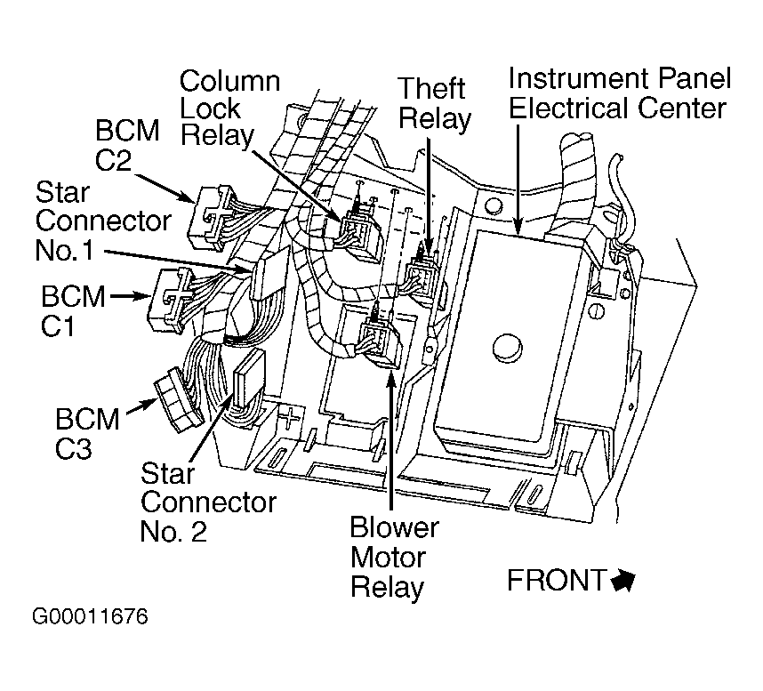 Courtesy of GENERAL MOTORS CORP.