Brake Indicator Is Inoperative
- If brake warning indicator does not light with parking brake engaged, go to next step. If brake warning indicator does not light when ignition switch is cycled from LOCK to RUN position, go to step 3). If brake warning indicator does not light when hydraulic brake system has low brake pressure in front or rear brakes only, go to step 4). If brake warning indicator does not light with neither a Electronic Brake Control Module (EBCM) problem nor a low brake pressure in front or rear only, go to step 5). If brake warning indicator is completely inoperative, go to step 7).
- Disconnect parking brake warning switch connector. Turn ignition on. Connect fused jumper between parking brake warning switch connector Light Blue wire and ground. If brake warning indicator comes on, check parking brake warning switch adjustment. If brake warning indicator does not come on, repair open circuit in Light Blue wire.
- Disconnect EBCM 10-pin connector. Turn ignition on. Connect fused jumper wire between EBCM connector terminal "H" (Purple wire) and ground. See Fig 1. If brake warning indicator comes on, see ANTI-LOCK BRAKE SYSTEM
article in BRAKES section. If brake warning indicator does not come on, repair open circuit in Purple wire.
- Disconnect brake pressure warning switch connector (Electronic Brake Control Module (EBCM) C3 connector). EBCM is located on left front frame rail, to left of transmission. C3 connector is on front side of EBCM. Turn ignition on. Connect fused jumper wire between brake pressure warning switch connector terminal "A" (Purple wire) and ground. If brake warning indicator does not come on, repair open circuit in Purple wire. If brake warning indicator does come on, check for open circuit in Black wire between brake pressure warning switch connector and ground. If Black wire is okay, diagnose brake pressure warning switch. See ANTI-LOCK BRAKE SYSTEM
article in BRAKES section.
- Disconnect EBCM 10-pin connector. Remove diode II in underhood fuse/relay center. Check resistance in Purple wire between EBCM connector terminal "H" and underhood fuse/relay center terminal K1. See Fig 1. If continuity is present, go to next step. If continuity is not present, repair open circuit in Purple wire.
- Turn ignition on. Connect test light between underhood fuse/relay center terminal L2 (Tan/White wire) and ground. If test light comes on, replace diode II. If test light does not come on, repair open circuit in Tan/White wire.
- Disconnect instrument cluster. Turn ignition on. Connect test light between instrument cluster Pink wire terminal B17 and ground. See Figure. If test light comes on, repair open circuit in Tan/White wire. If wire is okay, replace instrument cluster. If test light does not light, repair open circuit in Pink wire.
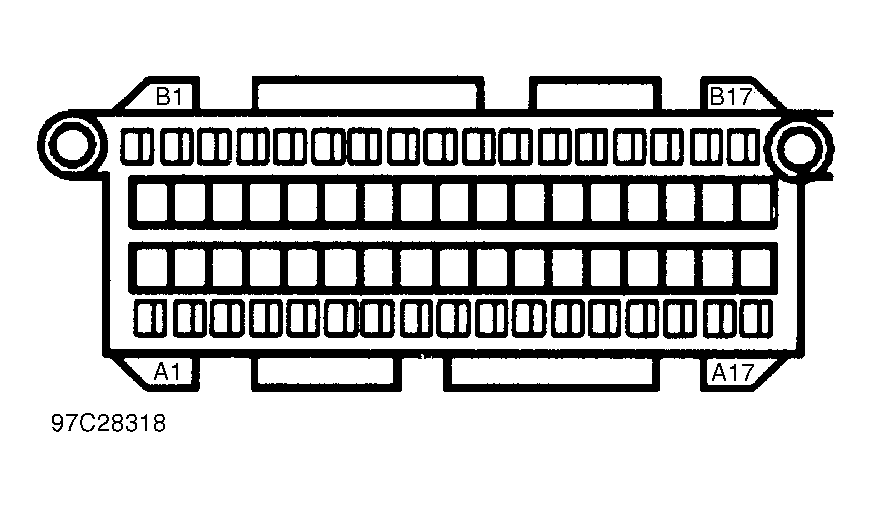 Courtesy of GENERAL MOTORS CORP.