Pinion Variance Procedure
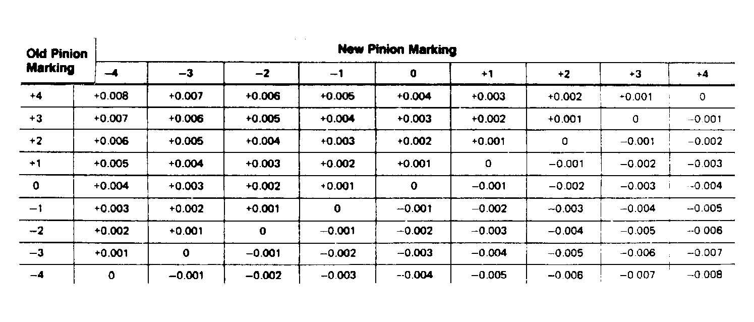
- Ring gear and pinion drive gears are machined as a unit. If gears have been removed, it is important that numbers stamped on ring and pinion set be factored into shim selection process. See Fig 1
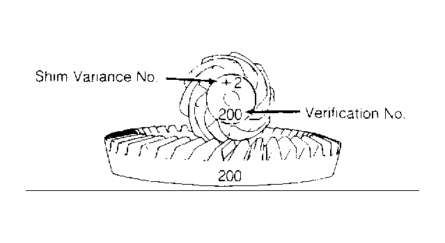
. Number stamped on pinion gear represents amount of adjustment necessary to obtain preferred position of gear set.
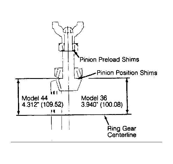
- Ideal position of gear set is 3.940" (100.08 mm) for 7 7/8" ring gear (Model 36) or 4.312" (109.52 mm) for 8 1/2" ring gear (Model 44) from back face of drive pinion gear to centerline of ring gear. Position is determined by thickness of shims placed between pinion bearing and pinion head.
- If "+2" is stamped on drive pinion gear, gear set will require .002" (.05 mm) less shimming than a drive pinion gear stamped zero. See Fig 2
. As shims are removed, distance between back face of drive pinion gear to centerline of ring gear is increased. See Fig 3
. If shims are added, distance between back face of drive pinion gear to centerline of ring gear is decreased.
- If ring gear and pinion drive gears are removed and are going to be reused, use a micrometer to measure shim(s) thickness and replace with shim(s) of equal thickness. If a new set of gears are used, locate old pinion marking and new pinion marking.
- Use these numbers and PINION VARIANCE CHART to determine correct shimming. See Fig 1
. If old pinion has a "+2" stamp and new pinion has a "-3" stamp, an additional .005" (.13 mm) of shims would be required.
 Courtesy of GENERAL MOTORS CORP.
 Courtesy of GENERAL MOTORS CORP.
 Courtesy of GENERAL MOTORS CORP.