Integrated Circuit Regulator
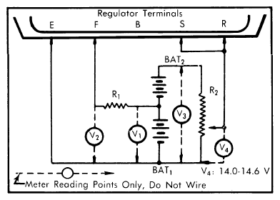
- Assemble a test circuit using the following components: One 10 ohm 3 watt resistor (R1
), one 0-300 ohm 3 watt variable resistor (R2
), two 12 volt batteries (BAT1
& BAT2
) and on one 0-30 volt DC voltmeter. See Fig 1 .
- Adjust variable resistor (R2
) until voltage at V4
reads the same as voltage at V3
(this should be all the way to one end of travel or 0 ohms).
- Connect the test circuit to the integrated circuit regulator terminals. Measure voltage at V1
and V2
. Voltage should measure 10-13 V at V1
and 0-2 V at V2
. Disconnect terminal S from circuit and measure voltage at V3
. Voltage at V3
should measure 20-26 V. Reconnect terminal S.
- Measure voltage at V2
while increasing resistance at R2
from 0 ohms. V2
should increase from 2 V up to 10-13 V. Stop increasing R2
when V2
reaches 10-13 V. If increase at V2
is interrupted at any point up to 10-13 V, while increasing resistance at R2
regulator is defective.
- Measure voltage at V4
while R2
is still at same setting, from previous step, that produced 10-13 V reading at V2
. If V4
is not within 14-14.6 V, regulator is defective.
 Courtesy of GENERAL MOTORS COMPANY
- Disconnect the wire attached to terminal "S" and connect it to terminal "B". Repeat procedure from step 4).
If V2
does not vary or V4
is not within 14.5-16.6 V, regulator is defective and replacement is necessary.