Removal Procedure
- Install the J 28467-A
in order to support the engine. See Special Tools and Equipment . Refer to Engine Support Fixture
in Engine Mechanical.
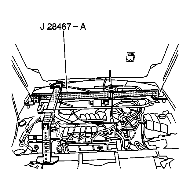 Courtesy of GENERAL MOTORS CORP.
- Raise and support the vehicle. Refer to Lifting and Jacking the Vehicle
in General Information.
- Remove the front tires and wheels. Refer to Tire and Wheel Removal and Installation
in Tires and Wheels.
- Remove the stabilizer shaft. Refer to Stabilizer Shaft Replacement (FE1 and FE3)
or Stabilizer Shaft Replacement (FE7)
in Front Suspension.
- Remove the bolts retaining the steering gear to the engine frame.
- Remove the ball joints from the steering knuckle. Refer to Lower Ball Joint Replacement (FE1, FE3)
in Front Suspension.
- Remove the front air deflector. Refer to Air Deflector Replacement - Front
in Body Front End.
- Remove the brake pressure modulator valve and bracket from the frame. Refer to Brake Pressure Modulator Valve (BPMV) Replacement
in Antilock Brake System.
- Disconnect the ESC sensor links from the lower control arm ball studs.
- Remove the secondary air injection pump assembly. Refer to Secondary Air Injection (AIR) Pump Replacement
in Engine Controls.
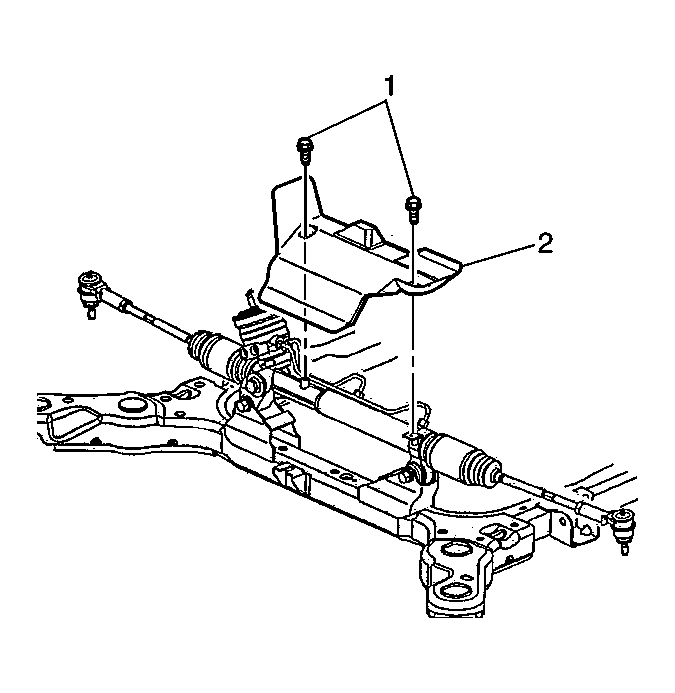
- Remove the steering gear heat shield fasteners (1) in order to remove the steering gear heat shield (2) and disconnect the electrical harness retainer that is mounted on the heat shield.
 Courtesy of GENERAL MOTORS CORP.
- Disconnect the electrical harness from the heat shield.
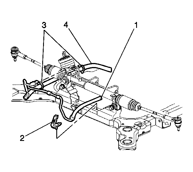
- Remove the brackets (2) retaining the power steering line (1) to the frame.
- Remove the retainer (3), retaining the power steering line (4) along the left side of the engine frame.
- Using mechanics wire, retain the steering gear to the body.
 Courtesy of GENERAL MOTORS CORP.
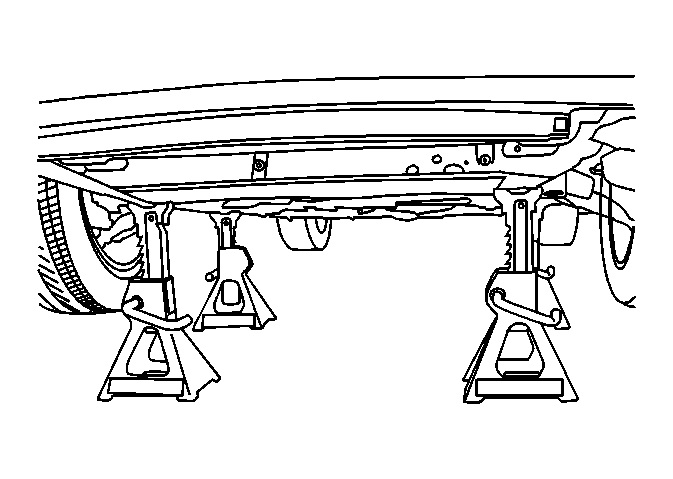
- Lower vehicle until the engine frame rests on the J 39580
or suitable jack stands. See Special Tools and Equipment .
 Courtesy of GENERAL MOTORS CORP.
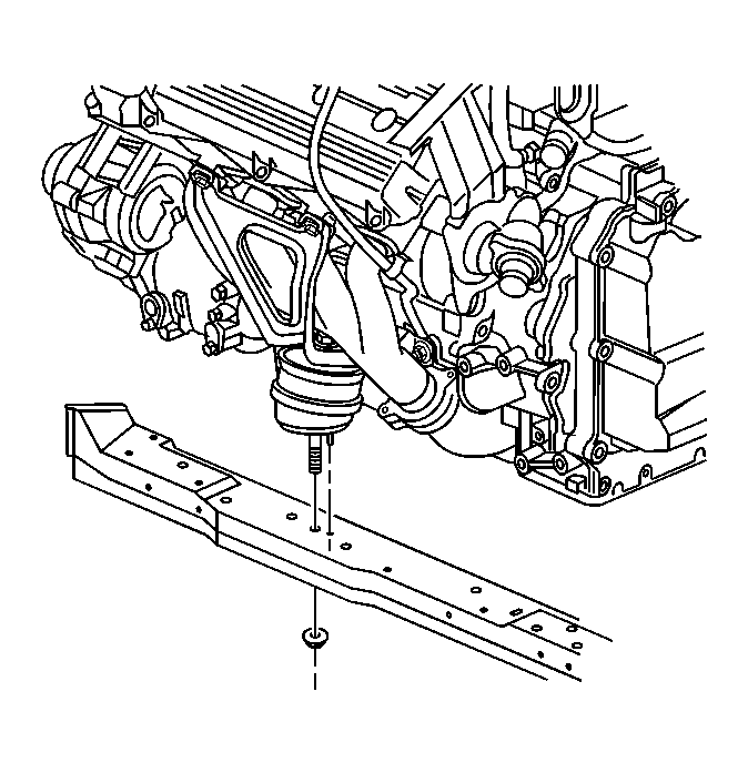
- Remove the fastener retaining the front engine mount to the engine frame.
 Courtesy of GENERAL MOTORS CORP.
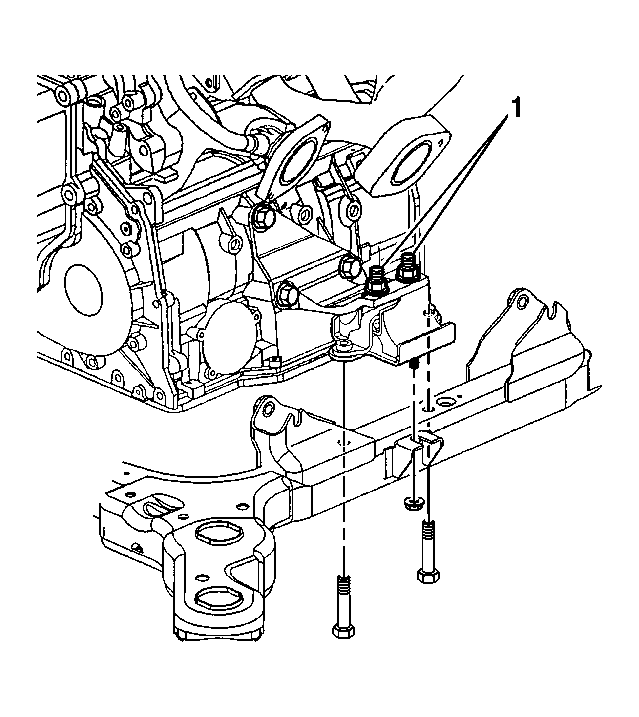
- Remove the fasteners retaining the rear transaxle mount (1) to the engine frame.
 Courtesy of GENERAL MOTORS CORP.
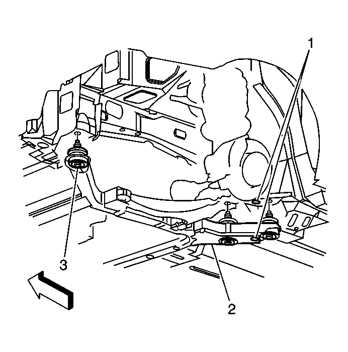
- Remove the engine frame insulator bolts (3) retaining the engine frame (2) to the vehicle.
 Courtesy of GENERAL MOTORS CORP.
- Raise vehicle away from engine frame.
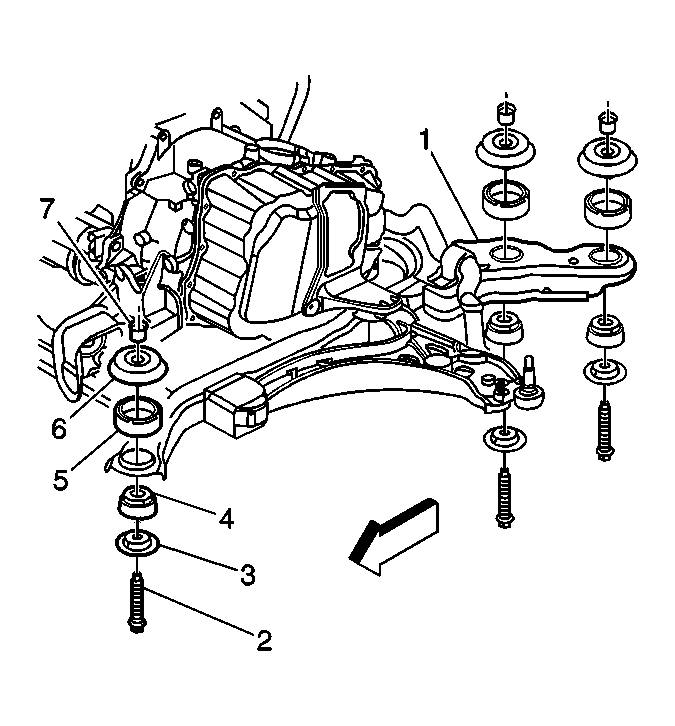
- Separate the engine frame insulators from the engine frame in the following order:
- Remove the bolts (2) from the engine frame (1).
- Remove the lower insulator retainer (3) from the lower insulator (4).
- Remove the lower insulator (4) from the engine frame (1).
- Remove the retainer (7) and the upper spacer (6) from the upper insulator (5).
- Remove the upper insulator (5) from the engine frame (1).
 Courtesy of GENERAL MOTORS CORP.
- Remove the control arms. Refer to Lower Control Arm Replacement (FE7)
or Lower Control Arm Replacement (FE1, FE3)
in Front Suspension.