Manual Shaft Shift Position Switch: Installation
- Install the manual shift shaft position switch (6), the manual shift shaft detent lever (4), the manual shift shaft assembly spacer (3), and the park pawl actuator (2) as an assembly. It may be necessary to push up on the park pawl in order to fully insert the park pawl actuator (2). See Figure.
- Fully insert the manual shift shaft (1) into the transmission case.
- Raise the transmission to its original position.
- Install the transmission support. See TRANSMISSION SUPPORT .
- Remove the transmission jack.
- Install the manual shift shaft detent spring (1). See Figure.
- Install the control valve body bolts (2) retaining the manual shift shaft detent spring. DO NOT tighten at this time.
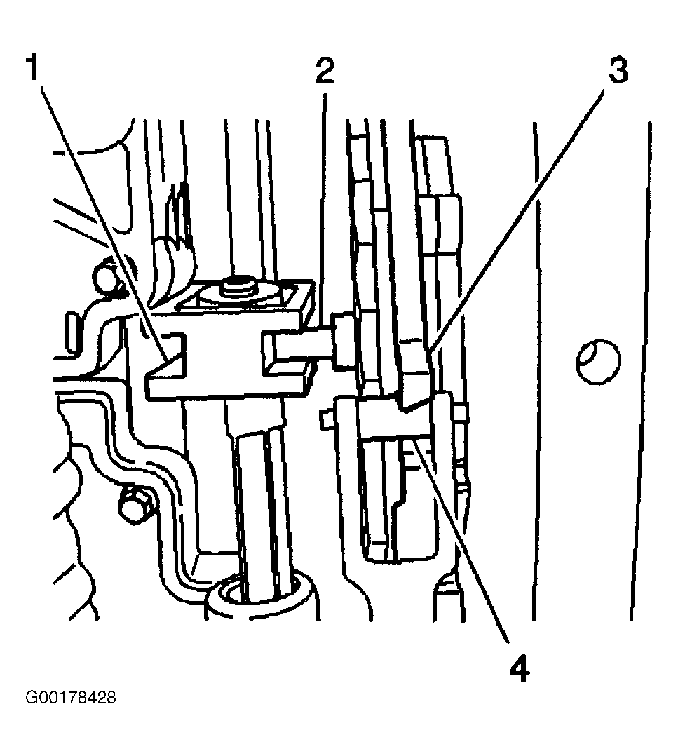
- Confirm that the manual shift shaft detent lever locating pin (2) is properly engaged with the manual valve link (1). See Fig 1.
- Confirm that the detent spring roller (4) is properly engaged with the manual shift shaft switch (3).
- Using a suitable pin punch (1). Install the manual shift shaft position switch retaining pin (2). See Figure.
- Connect the electrical connector to the manual shift shaft position switch.
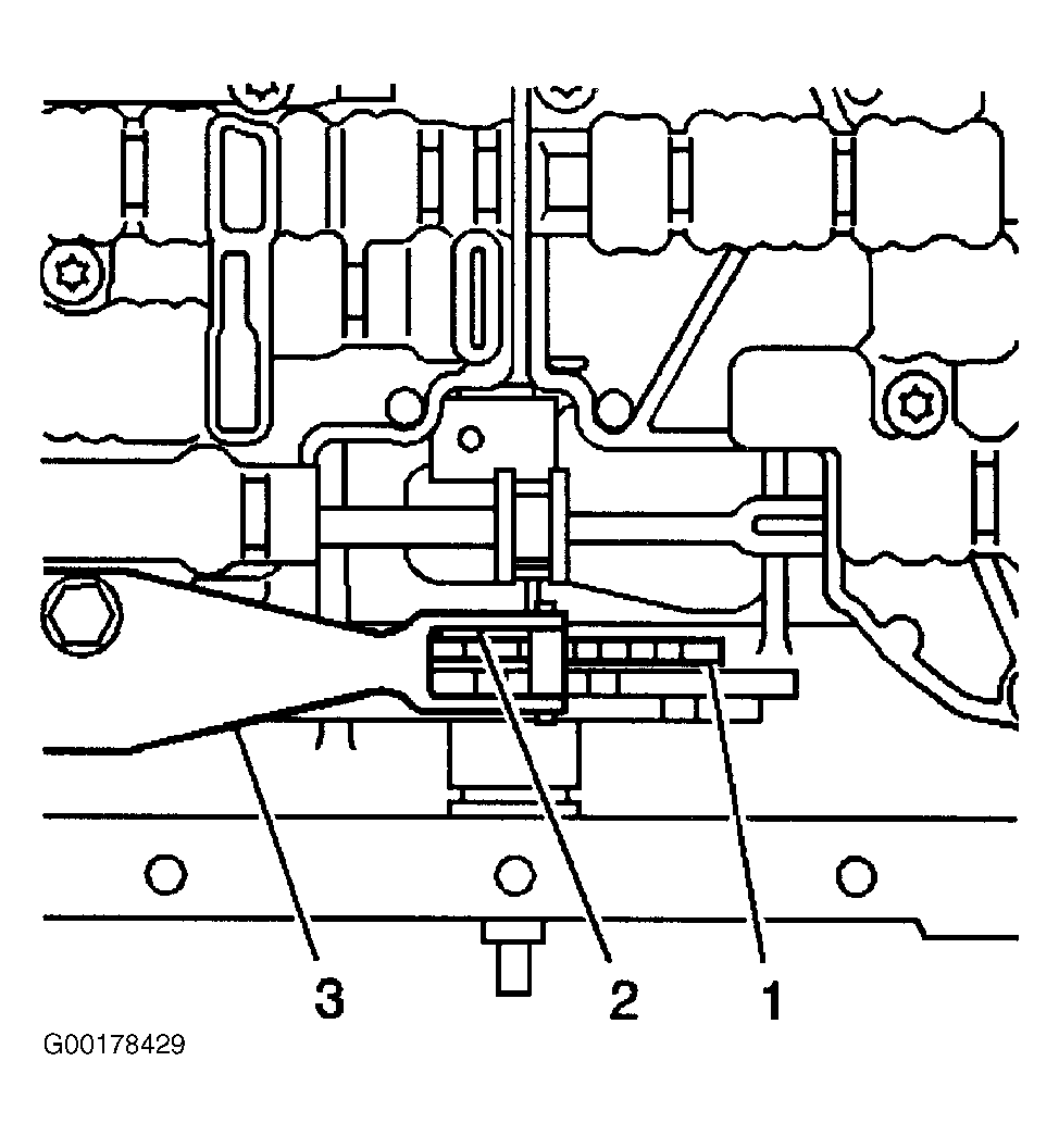
- Install a 0.8 mm spacer (2) between the manual shaft detent lever (1) and the manual shaft detent spring (3). See Fig 2.
- Tighten the detent spring bolts. See TORQUE SPECIFICATIONS .
- Remove the spacer (2).
- Install the transmission oil pan and filter.
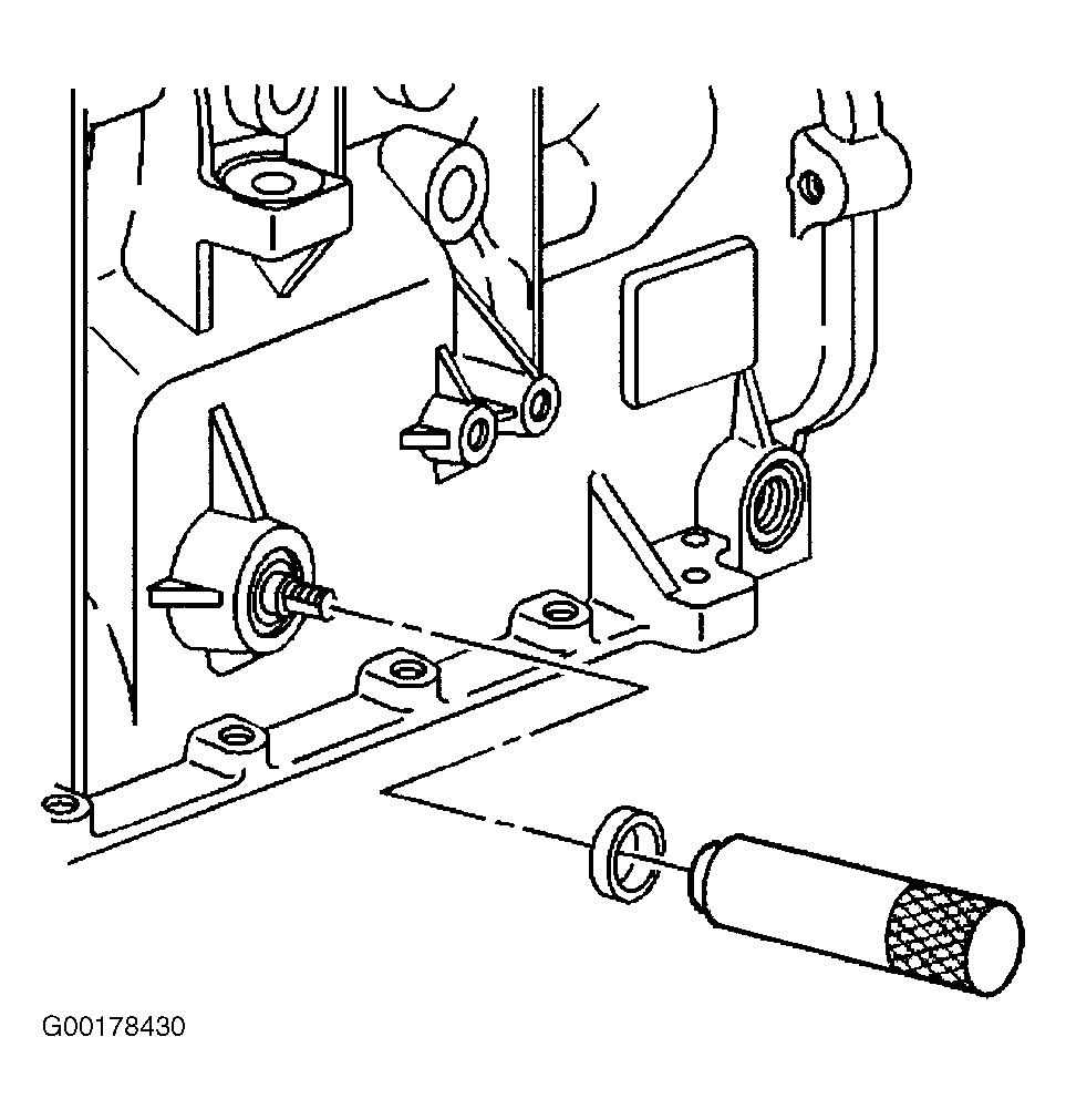
- If previously removed, install a new shaft seal using Seal Installer (J 44767). See Fig 3.
- Position the seal onto the seal installer before installing the seal into the transmission case.
- Carefully slide the seal and tool over the manual shift shaft and Insert the seal into the transmission until fully seated.
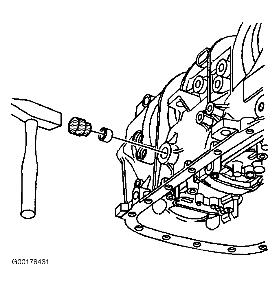
- If previously removed, install a new cup plug. Lubricate the cup plug with transmission fluid before installation. See Fig 4.
- Insert the cup plug into the transmission until flush with the transmission case.
- Remove the mechanics wire (2) securing front drive shaft (1) to the shift control lever (3). See Figure.
- Install the drive shaft coupler (1) to the transmission flange. See Figure. See appropriate DRIVESHAFT & UNIVERSAL JOINTS article in DRIVELINE/AXLES.
- Install the exhaust system components that were removed.
- Connect the shift linkage to the transmission manual shift shaft. See Figure.
- Install the transmission manual shift shaft nut. Tighten to specification. See TORQUE SPECIFICATIONS .
- Adjust the shift control linkage. See SHIFT CONTROL LINKAGE under ADJUSTMENTS.
- Lower the vehicle.
 Courtesy of GENERAL MOTORS CORP.
 Courtesy of GENERAL MOTORS CORP.
 Courtesy of GENERAL MOTORS CORP.
 Courtesy of GENERAL MOTORS CORP.