Test 16: Lumbar Support Inoperative - With Ac9
- Perform LUMBAR SUPPORT SYSTEM CHECK - WITH AC9
under TROUBLE SHOOTING. Go to next step.
- Operate system to verify customer complaint. If system operates normally, check for poor connections or broken wires inside of insulation which could cause an intermittent problem. If system does not operate normally, go to next step.
- Disconnect adaptive lumbar module connector. Turn ignition switch to ON position, engine off. Measure voltage between ground and vehicle side of adaptive lumbar module connector terminal "M" (Brown wire). See Fig 1
. If voltage is 9-16 volts, go to next step. If voltage is not 9-16 volts, go to step 22
.
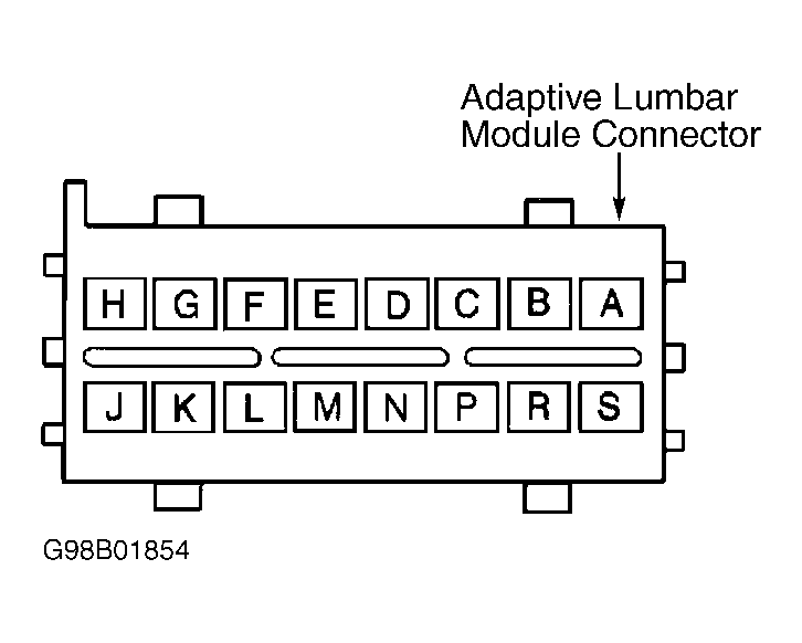 Courtesy of GENERAL MOTORS CORP.
- Measure voltage between ground and adaptive lumbar module connector terminal "S" (Orange wire). If voltage is 9-16 volts, go to next step. If voltage is not 9-16 volts, go to step 23
.
- Measure voltage between adaptive lumbar module connector terminals "S" (Orange wire) and "A" (Black wire). If voltage is 9-16 volts, go to next step. If voltage is not 9-16 volts, go to step 24
.
- Reconnect adaptive lumbar module connector. Disconnect lumbar switch connector. Measure voltage between ground and lumbar switch connector terminal "G" (Orange wire). See Figure
. If voltage is 9-16 volts, go to next step. If voltage is not 9-16 volts, go to step 17
.
- Reconnect lumbar switch connector. Measure voltage between ground and each adaptive lumbar module connector, lumbar switch input circuit. See WIRING DIAGRAMS
. If voltage from any circuit measures any voltage, go to step 18
. If voltage on all circuits measures zero volts, go to next step.
- Ensure adaptive lumbar module connector is connected. While operating lumbar switch in AUTO/ON direction, measure voltage between ground and adaptive lumbar module connector terminal "F" (Pink wire or White wire). If voltage is 6-10 volts, go to next step. If voltage is not 6-10 volts, go to step 12
.
- While operating lumbar switch in OFF direction, measure voltage between ground and adaptive lumbar module connector terminal "E" (Pink wire or White wire). If voltage is 6-10 volts, go to next step. If voltage is not 6-10 volts, go to step 13
.
- While operating lumbar switch in back direction, measure voltage between ground and adaptive lumbar module connector terminal "G" (Dark Blue wire). If voltage is 6-10 volts, go to next step. If voltage is not 6-10 volts, go to step 14
.
- While operating lumbar switch in forward direction, measure voltage between ground and adaptive lumbar module connector terminal "H" (Yellow wire). If voltage is 6-10 volts, go to step 19
. If voltage is not 6-10 volts, go to step 15
.
- Disconnect lumbar switch connector. Connect fused jumper wire (3-amp) between lumbar switch connector terminals "G" (Orange wire) and "B" (Pink wire or White wire). Measure voltage between ground and adaptive lumbar module connector terminal "F" (Pink wire or White wire). If voltage is 6-10 volts, go to step 20
. If voltage is not 6-10 volts, go to step 16
.
- Disconnect lumbar switch connector. Connect fused jumper wire (3-amp) between lumbar switch connector terminals "G" (Orange wire) and "C" (Pink wire or White wire). Measure voltage between ground and adaptive lumbar module connector terminal "E" (Pink wire or White wire). If voltage is 6-10 volts, go to step 20
. If voltage is not 6-10 volts, go to step 16
.
- Disconnect lumbar switch connector. Connect fused jumper wire (3-amp) between lumbar switch connector terminals "G" (Orange wire) and "A" (Dark Blue wire). Measure voltage between ground and adaptive lumbar module connector terminal "G" (Dark Blue wire). If voltage is 6-10 volts, go to step 20
. If voltage is not 6-10 volts, go to step 16
.
- Disconnect lumbar switch connector. Connect fused jumper wire (3-amp) between lumbar switch connector terminals "G" (Orange wire) and "F" (Yellow wire). Measure voltage between ground and adaptive lumbar module connector terminal "H" (Yellow wire). If voltage is 6-10 volts, go to step 20
. If voltage is not 6-10 volts, go to next step.
- Check appropriate lumbar switch circuit between adaptive lumbar module and lumbar switch for short to ground, high resistance, or open. See WIRING DIAGRAMS
. If problem is found, repair as necessary, then go to step 27
. If problem is not found, go to step 19
.
- Check Orange wire between lumbar switch and adaptive lumbar control module for short to ground, high resistance, or open. If problem is found, repair as necessary, then go to step 27
. If problem is not found, go to step 21
.
- Check lumbar switch circuits between adaptive lumbar module and lumbar switch for short to voltage. See WIRING DIAGRAMS
. If problem is found, repair as necessary, then go to step 27
. If problem is not found, go to step 20
.
- Perform a mechanical inspection of adaptive lumbar module assembly and bladders for air leaks and restricted air lines. If problem is found, repair as necessary, then go to step 27
. If problem is not found, go to step 21
.
- Check lumbar switch connector for poor connections. If problem is found, repair as necessary, then go to step 27
. If problem is not found, go to step 25
.
- Check adaptive lumbar module connector for poor connections. If problem is found, repair as necessary, then go to step 27
. If problem is not found, go to step 26
.
- Repair open or short to ground in Brown wire between adaptive lumbar module and rear junction block. After repairs, go to step 27
.
- Repair open or short to ground in Orange wire between adaptive lumbar module and rear junction block. After repairs, go to step 27
.
- Repair open in Black wire between adaptive lumbar module and ground. After repairs, go to step 27
.
- Replace lumbar switch. See POWER SEAT SWITCHES under REMOVAL & INSTALLATION in POWER SEATS - SEVILLE
article. After repairs, go to step 27
.
- Replace adaptive lumbar module. See LUMBAR MODULE under REMOVAL & INSTALLATION in POWER SEATS - SEVILLE
article. After repairs, go to next step.
- Operate system to verify repair. If system operates normally, repair is complete. If system does not operate normally, return to step 2
.