Module Test No. 2
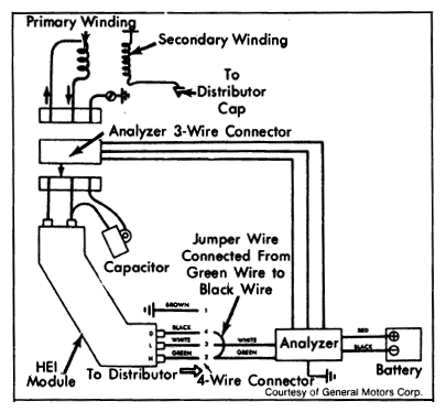
- Perform step 1 of MODULE (TEST NO. 1). Disconnect 4-wire connector from distributor to decoder. Connect analyzer Green clip to pin No. 2 (Green wire) that leads to module terminal H. Connect analyzer White wire clip to pin No. 3 (White wire) that leads to module terminal L. See Fig 1.
- Using a jumper wire, jumper between pin No. 2 (Green wire) and pin No. 4 (Black wire). Press and hold analyzer button down. A momentary Red light, then a continuous Green light indicates module is good, but pick-up coil is defective. If Red light stays on, module is defective.
 Courtesy of GENERAL MOTORS COMPANY