Power Window Components, Checking
 Courtesy of AUDI OF AMERICA, LLC
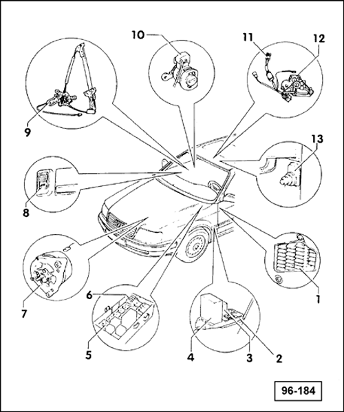
- Fuse Panel
- Auxiliary Relay Panel I
- Automatic Window Closing Relay -J261- (Comfort Relay)
- Power Window/Sunroof Control Module -J139-
- Auxiliary Relay Panel II
- Circuit Breakers -S43- and -S64-
- Generator (GEN) -C-
- Right Front Window Switch -E41-
- Right Window Motor -V15-
- Passenger's Door Handle Alarm Switch -F122-
- Sunroof Switch -E8-
- Sunroof Motor -V1-
- Door Contact Switch-Passenger Side -F3-
- Right Rear Door Window Motor -V27-
- Control Module for Central Locking/Alarm System/Interior Light Delay Control Module -V94-
- And infra-red central locking system, if applicable
- Left Rear Door Window Motor -V26-
- Left Rear Window Switch -E52-
- Driver's Door Handle Alarm Switch -F121-
- Door Contact Switch-Driver's Side -F2-
- Left Window Motor -V14-
- Switch Console
- Right Rear Window Switch -E54-
Special tools and workshop equipment required
- Digital multimeter Fluke 83 (US 1119)
- Connector test kit:VW 1594
- Sun VAT 40, Sun VAT 60
Test Conditions
- Battery OK.
- Circuit breakers -S43-, -S64- OK.
WARNING:
DO NOT damage, enlarge or bend connector terminals or cavities by forcing probes into them when performing electrical checks. Use :VW 1594
to make the necessary electrical connections.
| |
|
|
| |
Window Motor Current Draw (Installed), Checking |
|
| |
Note:
- Current draw may be close to tolerance limit, based on ambient (outside) temperature and mechanical resistance.
- Read stall current draw within 10 seconds, since circuit breaker in motor will open after 10 seconds.
- Power window control module interrupts power supply to driver's window after approximately 8-10 seconds (one touch down function).
-- Connect volt/amp tester Sun VAT 40, Sun VAT 60 (shown) or equivalent to positive (+) and negative (-) battery cables.-- Connect inductive amperage pickup to battery negative (-) cable.-- Switch ignition ON. |
|
| |
|
|
|
| |
|
|
Go to next page |
|
|
|
| |
|
|
|
|
|
|
|
| |
|
|
|
|
|
|
|
| |
Window Motor Current Draw (Installed), Checking |
|
| |
Note: When the ignition is switched ON, the tester will always indicate a certain current draw. This reading will vary according to operating conditions, electrical consumers being used, model of vehicle and equipment. -- Zero tester to compensate for initial current draw.-- Press individual window switches (open or close).-- Measure current draw during window switch operation.
- Must be 6-12 amps during window travel.
-- With window switch still activated, measure current draw when window has stopped at top or bottom.-- Must be 3-10 amps (stall current draw). |
|
| |
|
|
|
|
|
|
|
| |
Specified values NOT OK |
|
Specified readings OK, but window does not move |
|
| |
|
|
|
|
|
|
|
| |
Go to B next page. |
|
-- Check and repair wiring according to wiring diagram, or-- Replace window regulator or regulator motor. |
|
| |
|
|
|
|
|
|
|
| |
|
|
|
|
|
|
|
| |
|
|
|
|
End |
|
| |
|
|
|
|
|
|
|
 Courtesy of AUDI OF AMERICA, LLC Courtesy of AUDI OF AMERICA, LLC
|
| B |
| |
|
|
|
| |
Driver's Window Switch, Checking |
|
| |
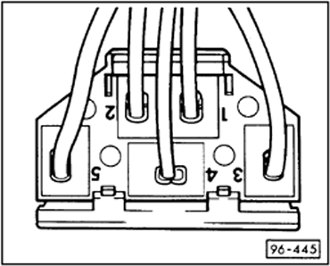
Note: The wiring from driver's window switch to the driver's is connected via a double connector -T2-. -- Remove window switch from driver's door trim panel.
- Leave all connectors attached.
-- Switch ignition ON.-- Set multimeter to measure voltage.-- Connect red test lead to terminal 4 and black test lead to terminal 3.
- Must read approximately 12 volts.
-- Connect red test lead to terminal 4 and black test lead to terminal 5.
- Must read approximately 12 volts.
-- Connect multimeter test leads to terminal 3 (black) and terminal 2 (red) of driver's window switch connector.-- Operate switch to lower window.
- Must read approximately 12 volts.
-- Connect multimeter test leads to terminal 5 (black) and terminal 1 (red) of driver's window switch connector.-- Operate switch to raise window.
- Must read approximately 12 volts.
|
|
| |
|
|
|
|
|
|
|
| |
|
|
Go to C next page. |
|
|
|
| |
|
|
|
|
|
|
|
Courtesy of AUDI OF AMERICA, LLC
|
| C |
| |
|
|
|
| |
Automatic "One Touch Down" Function, Checking |
|
| |
-- Switch ignition ON.-- Raise driver's door window fully.-- Set multimeter to measure voltage.-- Connect black test lead to terminal 3 and red test lead to terminal 2 of driver's window switch connector. Note: During "one touch down" window operation, voltage can be measured for approximately 10 seconds. -- Press driver's window switch (to lower window) and release.
- Must read approximately 12 volts.
- Window must lower automatically.
-- Connect black test lead to terminal 5 and red test lead to terminal 1.-- Press driver's window switch (to raise window) and release.
- Must read approximately 12 volts.
- Window must close automatically.
|
|
| |
|
|
|
|
|
|
|
| |
|
|
Go to -C1- next page. |
|
|
|
| |
|
|
|
|
|
|
|
Courtesy of AUDI OF AMERICA, LLC
|
| -C1- |
| |
|
|
|
| |
Right Front, Right Rear, and Left Rear Window Switches, in Driver's Door, Checking |
|
| |
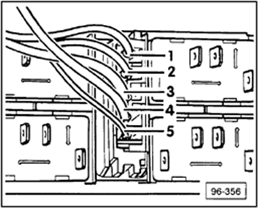
-- Do not remove window switches from driver's door console.-- Leave switch connectors attached.-- Check window switches in sequence.-- Switch ignition ON.-- Connect multimeter black test lead to terminal 3 and red test lead to terminal 4, then connect black test lead to terminal 5 and red test lead to terminal 4 of right front window switch connector.
|
|
| |
|
|
|
|
|
|
|
| |
|
|
Go to -C2- next page. |
|
|
|
| |
|
|
|
|
|
|
|
Courtesy of AUDI OF AMERICA, LLC
|
| -C2- |
| |
|
|
|
| |
-- Connect multimeter black test lead to terminal 3 and red test lead to terminal 2 of right front window switch connector.-- Operate switch to lower window.
- Must read approximately 12 volts.
|
|
| |
|
|
|
|
|
|
|
| |
-- Connect multimeter black test lead to terminal 3 and red test lead to terminal 1 of right front window switch connector.-- Operate switch to raise window.
- Must read approximately 12 volts.
|
|
| |
|
|
|
|
|
|
|
| |
-- Repeat test for right and left rear window switches. |
|
| |
|
|
|
|
|
|
|
| |
|
|
Go to D next page. |
|
|
|
| |
|
|
|
|
|
|
|
 Courtesy of AUDI OF AMERICA, LLC Courtesy of AUDI OF AMERICA, LLC
|
| D |
| |
|
|
|
| |
Rear Window Lockout (Safety) Switch, Checking |
|
| |
-- Remove window switch console from driver's door trim panel.
- Leave window lockout switch installed.
- Leave wire connectors attached.
- Lockout switch OFF.
- Button UP.
-- Set multimeter to measure voltage and connect test leads alternately between ground (GND) and terminal 1, then ground and terminal 4 of lockout switch connector.
- Must read 12 volts in each case.
-- Connect multimeter leads alternately between ground and terminal 2, then ground and terminal 3 of lockout switch connector.
- Must read 0 volts in each case.
-- Switch window lockout switch ON.
-- Repeat voltage check at terminals 2 and 3.
- Must read approximately 12 volts.
|
|
| |
One or more specified values NOT OK |
All specified values OK |
|
| |
|
|
|
|
|
|
|
| |
Go to next page. |
|
Go to F Refer to POWER WINDOW COMPONENTS, CHECKING => Right Front Door Operating Switch, Function, Voltage Supply, Checking . |
|
| |
|
|
|
|
|
|
|
Courtesy of AUDI OF AMERICA, LLC
|
| |
| |
-- Check and repair wiring according to wiring diagram, or-- Check window switches for continuity -D1-. Refer to POWER WINDOW COMPONENTS, CHECKING => Power Window Switches, Checking Continuity , or-- Check rear window lockout (safety) switch in driver's door for continuity -D2-. Refer to POWER WINDOW COMPONENTS, CHECKING => Rear Window Lockout (Safety) Switch, Checking Continuity forward. |
|
| |
|
|
|
|
|
| |
|
Go to E Refer to POWER WINDOW COMPONENTS, CHECKING - Rear Window Operating Switches, Function, Voltage Supply, Checking . |
|
|
| |
|
|
|
|
|
 Courtesy of AUDI OF AMERICA, LLC Courtesy of AUDI OF AMERICA, LLC
|
| -D1- |
| |
|
|
|
| |
Power Window Switches, Checking Continuity |
|
| |
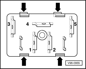
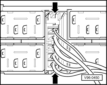
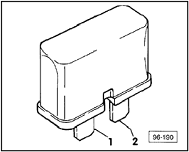
-- Windows fully raised.-- Use small screwdriver, pry (at arrows) switch from retainer.
- Reinstall by pressing in from bottom until switch "clicks in".
-- Disconnect plug connectors.-- Set multimeter to measure resistance (Ω), and connect test leads alternately between terminals 5 and 2, then terminals 3 and 1 of window switch.
- Must read 0 Ω (continuity) in each case.
-- Connect multimeter to terminals 4 and 2 of window switch.
- Must read ∞ Ω (no continuity).
-- Operate switch to lower window.
- Must read 0 Ω (continuity).
-- Connect multimeter test leads between terminals 4 and 1 of window switch.
- Must read ∞ Ω (no continuity).
-- Operate switch to raise window.
- Must read 0 Ω (continuity).
|
|
| |
One or more specified values NOT OK |
|
| |
|
|
|
|
|
|
|
| |
|
-- Replace window switch. |
|
|
| |
|
|
|
|
|
|
|
| |
|
|
End |
|
|
|
| |
|
|
|
|
|
|
|
 Courtesy of AUDI OF AMERICA, LLC Courtesy of AUDI OF AMERICA, LLC
|
| -D2- |
| |
|
|
|
| |
Rear Window Lockout (Safety) Switch, Checking Continuity |
|
| |
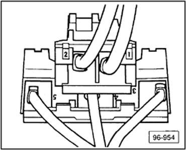
-- Insert small screwdriver into openings (arrows) and press lugs toward center of switch.-- Remove switch.
- Reinstall by pressing in switch from bottom until "clicks" into place.
-- Disconnect plug connectors.-- Ensure safety switch is OFF.
-- Set multimeter to measure resistance (Ω) range, and connect test leads alternately to terminals -1- and -2-, then -3- and -4- of switch.
- Must read ∞ Ω (no continuity) in each case.
-- Switch safety switch ON.
- Button down.
- Must read 0 Ω (continuity) in each case.
|
|
| |
One or more specified values NOT OK |
|
| |
|
|
|
|
|
|
|
| |
|
-- Replace rear window lockout (safety) switch. |
|
|
| |
|
|
|
|
|
|
|
| |
|
|
End |
|
|
|
| |
|
|
|
|
|
|
|
 Courtesy of AUDI OF AMERICA, LLC Courtesy of AUDI OF AMERICA, LLC
|
| E |
| |
|
|
|
| |
Rear Window Operating Switches, Function, Voltage Supply, Checking |
|
| |
Note: Window lockout switch in driver's door switch panel must ON (button down) when performing checks otherwise no volt. is supplied. -- Remove inside door handle with switch.-- Leave all wire connectors attached.-- Switch ignition ON.-- Set multimeter to measure voltage.-- Connect black test lead to terminal 3 and red test lead to terminal 4 of window switch connectors.
- Must read approximately 12 volts.
-- Connect black test lead to terminal 5 and red test lead to terminal 4 of window switch connectors.
- Must read approximately 12 volts.
-- Connect multimeter black test lead to terminal 3 and red test lead to terminal 2 of window switch connector.-- Operate switch to lower window.
- Must read approximately 12 volts.
-- connect multimeter black test lead to terminal 3 and red test lead to terminal 1 of window switch connector.-- Operate switch to raise window.
- Must read approximately 12 volts.
|
|
| |
|
|
|
|
|
|
|
| |
|
|
Go to next page |
|
|
|
| |
|
|
|
|
|
|
|
| |
|
|
|
|
|
|
|
|
|
| |
One or more specified values NOT OK |
All specified values OK |
|
| |
|
|
|
|
|
|
|
|
|
| |
-- Remove door trim.-- Check and repair wiring from window switch to window regulator motor for open circuits according to wiring diagram.-- Check continuity of operating switch -D1-. Refer to POWER WINDOW COMPONENTS, CHECKING => Power Window Switches, Checking Continuity . |
|
|
-- Remove door trim as required.-- Check and repair wiring between operating switch and window regulator motor. If OK: -- Replace window regulator motor and/or window regulator. |
|
| |
|
|
|
|
|
|
|
|
|
| |
|
End |
|
|
|
End |
|
| |
|
|
|
|
|
|
|
|
|
 Courtesy of AUDI OF AMERICA, LLC Courtesy of AUDI OF AMERICA, LLC
|
| |
|
|
F |
|
|
|
| |
|
|
|
| |
Right Front Door Operating Switch, Function, Voltage Supply, Checking |
|
| |
-- Remove inside door handle with switch.-- Leave plug connector attached.-- Switch ignition ON.-- Set multimeter to measure voltage.-- Connect black test lead to terminal 3 and red test lead to terminal 4 of window switch connector.
- Must read approximately 12 volts.
-- Connect black test lead to terminal 5 and red test lead to terminal 4 of window switch connector.
- Must read approximately 12 volts.
-- Connect multimeter black test lead to terminal 3 and red test lead to terminal 2.-- Operate switch to lower window.
- Must read approximately 12 volts.
-- Connect multimeter black test lead to terminal 5 and red test lead to terminal 1.
- Must read approximately 12 volts.
|
|
| |
One or more specified values NOT OK |
All specified values OK |
|
| |
|
|
|
|
|
|
|
| |
Go to -F1- next page. |
|
|
Go to -F2- next page. |
|
| |
|
|
|
|
|
|
|
| |
-F1- |
|
|
-F2- |
|
| |
|
|
|
|
|
|
|
| |
-- Check and repair wiring according to wiring diagram, or-- Check continuity of operating switch -D1-. Refer to POWER WINDOW COMPONENTS, CHECKING => Power Window Switches, Checking Continuity . |
|
|
-- Check and repair wiring between operating switch and window regulator motor, or If OK: -- Replace window regulator motor or regulator. Note: Window regulator motor can be replaced without removing window regulator |
|
| |
|
|
|
|
|
|
|
| |
End |
|
|
|
|
|
| |
|
|
|
|
|
|
|
| |
|
|
|
|
|
|
|
| |
|
|
|
|
|
|
|
| |
|
|
|
End |
|
| |
|
|
|
|
|
|
|
 Courtesy of AUDI OF AMERICA, LLC Courtesy of AUDI OF AMERICA, LLC
|
| |
|
|
G |
|
|
|
| |
|
|
|
| |
Right Front Door Operating Switch, Function, Voltage Supply, Checking |
|
| |
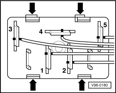
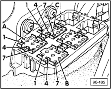
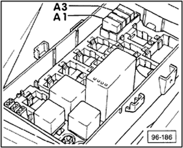
-- Ignition switched OFF.-- Remove panel cover in left side footwell.-- Remove control module from auxiliary relay panel II.
- Located in plenum chamber.
-- Set multimeter to measure voltage, and connect red test lead to terminal 2 of relay socket -A- and black test lead to ground.
-- Connect multimeter red test lead to terminal 7 of relay socket -A- and black test lead to ground.-- Connect multimeter red test lead to terminal 1 of relay socket -A- and black test lead to ground.-- Switch ignition ON.
|
|
| |
One or more specified values NOT OK |
All specified values OK |
|
| |
|
|
|
|
|
|
|
| |
Go to next page. |
|
|
Go to H Refer to POWER WINDOW COMPONENTS, CHECKING => Door Contact Switch, Checking Continuity to Power Window/Sunroof Control Module -J139- . |
|
| |
|
|
|
|
|
|
|
 Courtesy of AUDI OF AMERICA, LLC Courtesy of AUDI OF AMERICA, LLC
|
| |
| |
-- Check and repair wiring according to wiring diagram, or-- Check power window circuit breaker -S43-. Refer to POWER WINDOW COMPONENTS, CHECKING - Rear Window Operating Switches, Function, Voltage Supply, Checking , in auxiliary relay panel II, in plenum chamber, position -A3-. |
|
| |
|
|
|
|
|
| |
|
End |
|
|
| |
|
|
|
|
|
Courtesy of AUDI OF AMERICA, LLC
|
| |
|
|
H |
|
|
|
| |
|
|
|
| |
Door Contact Switch, Checking Continuity to Power Window/Sunroof Control Module -J139- |
|
| |
-- Open driver's door.-- Set multimeter to measure resistance (Ω) and connect red test lead to terminal 5 of relay socket -A- and black test lead to ground.
- Must read 0 Ω (continuity).
-- Manually press driver's door contact switch.
- Must read ∞ Ω (no continuity).
|
|
| |
One or more specified values NOT OK |
All specified values OK |
|
| |
|
|
|
|
|
|
|
| |
-- Check and repair wiring according to wiring diagram, or-- Replace malfunctioning switch. |
|
|
-- Replace power window/sunroof control module -J139- in auxiliary relay panel II or,-- Check driver's window switch. |
|
| |
|
|
|
|
|
|
|
| |
End |
|
|
End |
|
| |
|
|
|
|
|
|
|
 Courtesy of AUDI OF AMERICA, LLC Courtesy of AUDI OF AMERICA, LLC
|
| |
|
|
|
| |
Power Window Circuit Breakers, Checking |
|
| |
-- Remove circuit breaker from auxiliary relay panel II.-- Set multimeter to measure resistance (Ω), and connect test leads between terminals 1 and 2 of circuit breaker.
- Must read approximately 0 Ω (continuity).
|
|
| |
Specified value NOT OK |
Specified value OK |
|
| |
|
|
|
|
|
|
|
| |
-- Replace circuit breaker. |
|
|
-- Check and repair wiring according to wiring diagram. |
|
| |
|
|
|
|
|
|
|
| |
End |
|
|
End |
|
| |
|
|
|
|
|
|
|