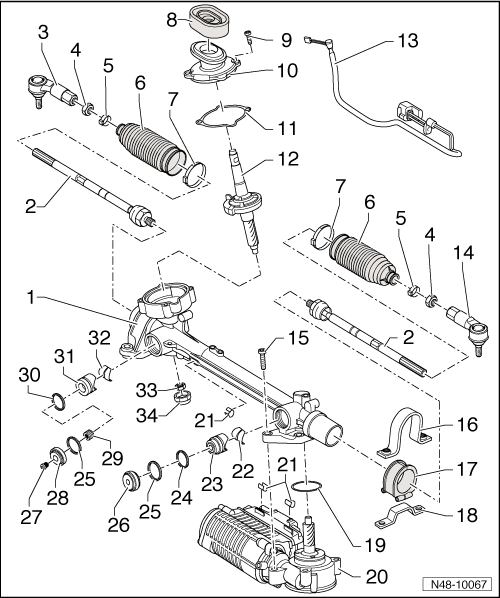
Steering Gear Overview, Generation I
 Courtesy of AUDI OF AMERICA, LLC
- Steering Gear Housing
- Tie Rod
- 100 Nm
- Removing and installing, refer to TIE ROD .
- Left Tie Rod End
- Check dust caps for damage and correct seating.
- Nut
- 55 Nm
- Nut must be counter held on tie rod end using a wrench when loosening and tightening.
- Spring Clamp
- Boot
- Removing and installing, refer to BOOT .
- Check for damage.
- Must not be twisted after toe is adjusted.
- Clamp
- Always replace if removed.
- Install a new clamp with locking pliers VAS 6199.
- Gasket
- Between steering gear and vehicle interior.
- Bolt
- Cover
- Gasket
- Always replace if removed.
- Steering Pinion with Steering Angle Sensor
- Sensor Wire
- Removing and installing, refer to SENSOR WIRE .
- Electrical connection between the sensor and servo motor with control module.
- Right Tie Rod End
- Check dust caps for damage and correct seating.
- Bolt
- Clamp with Nuts
- Removing and installing, refer to RUBBER BUSHING .
- Always replace if removed.
- Rubber Bushing
- Bracket
- Seal
- Always replace if removed.
- Servo Motor with Control Module
- Removing and installing, refer to SERVOMOTOR WITH CONTROL MODULE .
- With power steering control module -J500-.
- With electromechanical power steering motor -V187-.
- With Engine Speed (RPM) sensor -G577-.
- Can be tested in "Guided Fault Finding" using the vehicle diagnosis, testing and information systemVAS 5051B.
- Clip
- Contact Foil
- Not an individual component, is installed on the thrust piece.
- Coat with supplied grease G 052 192 A1 on contact side facing steering rack.
- Hydraulic Thrust Piece
- Seal
- Installed on the hydraulic thrust piece.
- Seal
- Insert into steering gear housing between thrust piece and adjustment screw.
- Adjustment Bolt
- For the hydraulic thrust piece.
- Always replace if removed.
- Rubber Plug
- Adjustment Bolt
- For the mechanical thrust piece.
- Always replace if removed.
- Spring
- Seal
- Installed on mechanical thrust piece.
- Mechanical Thrust Piece
- Contact Foil
- Not an individual component, is installed on the thrust piece.
- Coat with supplied grease G 052 192 A1 on contact side facing steering rack.
- Nut
- 25 Nm
- Always replace if removed.
- Screw Plug
- 65 Nm
- Fill with grease G 052 192 A1 before installing.
- Coat thread with LOCTITE®5910.