Auto-Check Coding Procedure
- Access back of instrument cluster. Disconnect Green 26-pin harness connector. Connect Adapter Harness (VAG 1598/4) to Green 26-pin harness connector. Connect adapter harness to instrument cluster and Test Box (1598). Turn ignition switch to RUN position. Measure voltage between ground and terminal No. 24 at test box. If battery voltage exists, go to next step. If battery voltage does not exist, repair open in wiring. See WIRING DIAGRAMS.
- Adjust coding switch to position No. 2. See Fig 1
. Turn ignition switch off. Disconnect test equipment. Connect all harness connectors. Install instrument cluster. Retest auto-check coding.
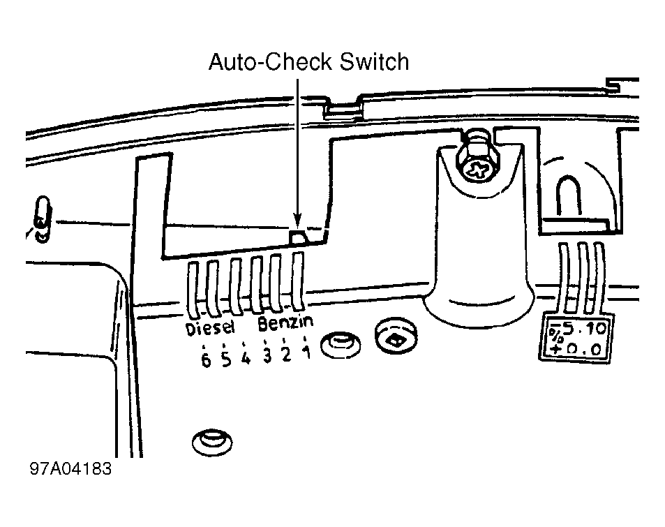 Courtesy of AUDI OF AMERICA, INC.