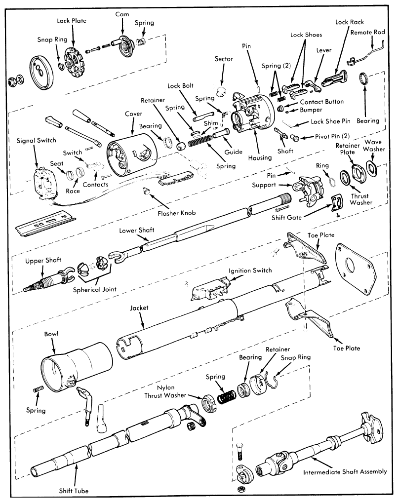
- Disconnect battery negative cable. Remove steering wheel and horn button. Remove shift lever retaining pin and lever (if column shift). Loosen cover screws and remove cover. Using suitable lock plate compressor tool (J-23653 or equivalent), depress lock plate and remove snap ring.
CAUTION:
Lock plate is under strong spring pressure. Do not attempt to remove snap ring without spring compressor.
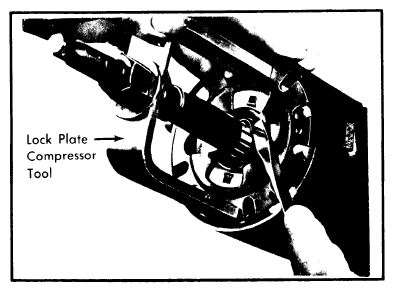 Courtesy of AMERICAN MOTORS/RENAULT CORP.
- Loosen lock plate compressor nut and remove the tool, lock plate, directional signal cancelling cam, upper bearing preload spring, bearing race seat and bearing race.
- Place signal switch in right turn position and remove handle. Depress hazard warning light switch and remove button by turning it counterclockwise.
- Remove signal wire harness connector block from mounting bracket on lower right side of column. If equipped with Cruise Command, mark position of wires for correct assembly, then remove signal switch and wire harness from column.
- Use a small wire hook to remove buzzer switch and clip as an assembly. Place lock in "ON" position. Hook wire into buzzer switch contacts and pull out and up to remove contacts and buzzer as an assembly.
NOTE:
Do not attempt to remove switch separately as contacts may fall inside column assembly.
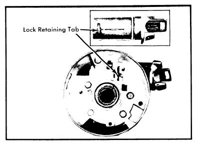 Courtesy of AMERICAN MOTORS/RENAULT CORP.
- Place key in "LOCK" position and, with a small screwdriver, depress lock cylinder retaining tab to remove cylinder. With Hornet and Gremlin models, remove shift quadrant. Quadrant is retained by a spring clip located behind quadrant indicator housing, remove clip with needle nose pliers. Remove shift quadrant mounting bracket and light socket (if equipped). Disconnect shift quadrant cable under steering column. Unscrew tilt release handle.
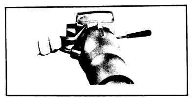 Courtesy of AMERICAN MOTORS/RENAULT CORP.
- Remove upper cover from column, then remove the lock sector tension spring. The spring must be unhooked from the lock bolt. Remove the Tru-arc snap ring from lock sector shaft and remove the sector, shaft and lock pin.
 Courtesy of AMERICAN MOTORS/RENAULT CORP.
 Courtesy of AMERICAN MOTORS/RENAULT CORP.
- Use release handle to place upper housing in full UP position. Insert screwdriver into slot in tilt spring retainer. Depress the retainer approximately 3/16" and rotate 1/8 turn counterclockwise to remove retainer and spring.
CAUTION:
Spring is under high compression.
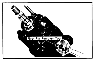
- With upper housing in straight position, remove two pivot pins using tool J-21854-1 or equivalent. Lift tilt handle to disengage lock shoes and to remove bearing housing assembly.
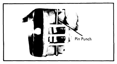 Courtesy of AMERICAN MOTORS/RENAULT CORP.
- If servicing lock shoes, release lever or springs, remove release lever pin and lock shoe pin. Hold lock shoe springs in compression to relieve the load on pins. Remove steering shaft from top of column. The flexible joint is disassembled by folding the shaft 90°.
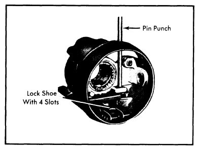 Courtesy of AMERICAN MOTORS/RENAULT CORP.
- Remove ignition switch, lock rack and rod, lower bearing retainer snap ring, retainer and bearing. Remove shift tube retainer ring and thrust washer. Use tool J-23072 to remove shift tube.
- Take out retainer plate by rotating shift bowl clockwise and sliding plate out of jacket notches. Tip plate down toward shift bowl hub at 12 o'clock position and remove bottom side of plate first. Remove wave washer and shift bowl from column.
- Apply thin coat of lithium grease (or equivalent) to all friction surfaces. Reassemble all components in reverse order of removal procedure.
NOTE:
For torque specifications, see American Motors Collapsible Steering Column in this section.