Audio Unit Connector for Inputs and Outputs (2014 2015)
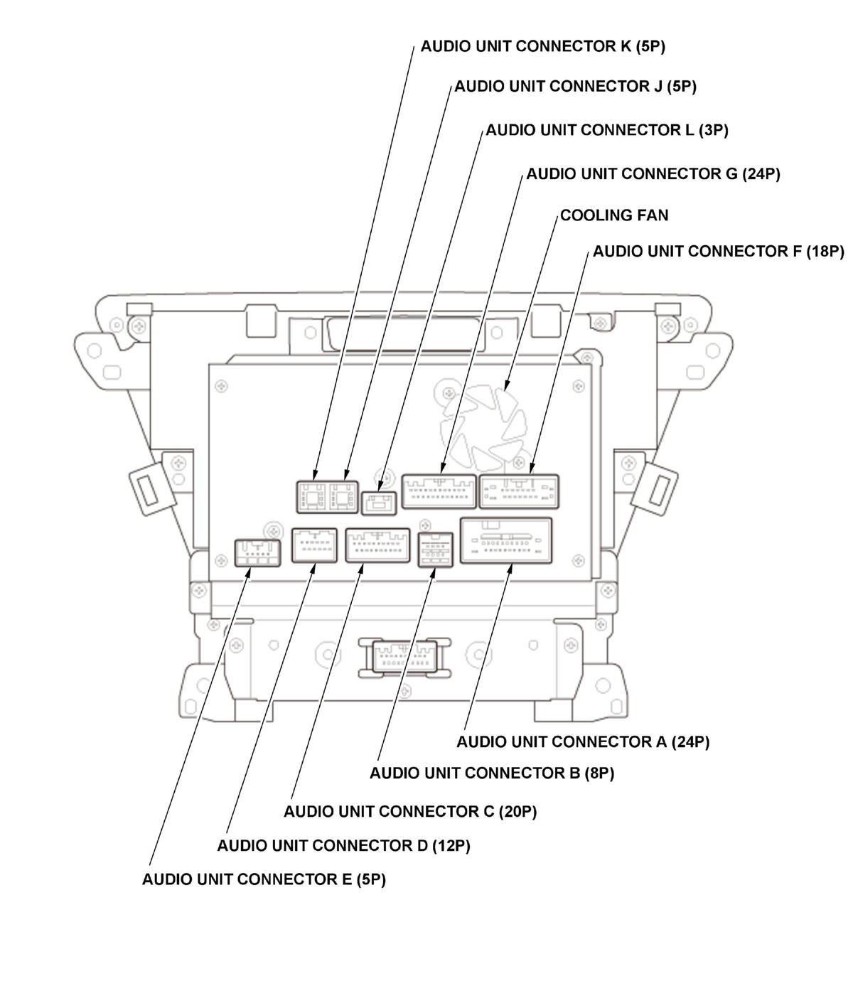 Courtesy of HONDA, U.S.A., INC. Courtesy of HONDA, U.S.A., INC.
|
AUDIO UNIT CONNECTOR A (24P)
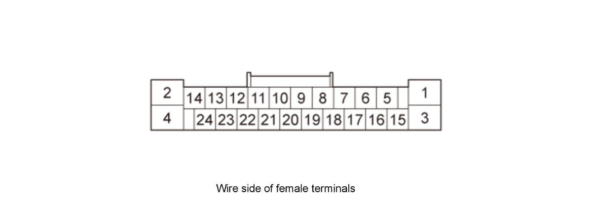 Courtesy of HONDA, U.S.A., INC. Courtesy of HONDA, U.S.A., INC.
|
| Cavity |
Wire Color |
Terminal Name |
Description |
| A1 |
BLK |
SGND |
Ground for audio unit (G505) |
| A2 |
BLU |
B-CAN_L |
B-CAN bus communication signal |
| A3 |
ORN |
+B RADIO |
Continuous power source |
| A4 |
PNK |
B-CAN_H |
B-CAN bus communication signal |
| A5 |
Not used |
Not used |
- - - |
| A6 |
Not used |
Not used |
- - - |
| A7 |
Not used |
Not used |
- - - |
| A8 |
Not used |
Not used |
- - - |
| A9 |
Not used |
Not used |
- - - |
| A10 |
Not used |
Not used |
- - - |
| A11 |
Not used |
Not used |
- - - |
| A12 |
GRN |
SCTY (2) |
Security signal from center display unit |
| A13 |
LT BLU |
K-LINE |
Detects scan tool signal (serial data) |
| A14 |
Not used |
Not used |
- - - |
| A15 |
BLU |
FL PRE IN+ |
Outputs sound signal for left front channel |
| A16 |
YEL |
FL PRE IN- |
Outputs sound signal for left front channel |
| A17 |
Not used |
Not used |
- - - |
| A18 |
Not used |
Not used |
- - - |
| A19 |
LT BLU |
FR PRE IN+ |
Outputs sound signal for right front channel |
| A20 |
GRY |
FR PRE IN- |
Outputs sound signal for right front channel |
| A21 |
PNK |
RADIO SW (B) |
Outputs signal for stereo amplifier and ANC/active sound control unit switching on/off |
| A22 |
Not used |
Not used |
- - - |
| A23 |
Not used |
Not used |
- - - |
| A24 |
PUR |
B ACC |
Power source for accessories |
AUDIO UNIT CONNECTOR B (8P)
 Courtesy of HONDA, U.S.A., INC. Courtesy of HONDA, U.S.A., INC.
|
| Cavity |
Wire Color |
Terminal Name |
Description |
| B1 |
Not used |
Not used |
- - - |
| B2 |
Not used |
Not used |
- - - |
| B3 |
Not used |
Not used |
- - - |
| B4 |
LT GRN |
ANC CK2 |
Outputs ANC test signal |
| B5 |
Not used |
Not used |
- - - |
| B6 |
Not used |
Not used |
- - - |
| B7 |
Not used |
Not used |
- - - |
| B8 |
Not used |
Not used |
- - - |
AUDIO UNIT CONNECTOR C (20P)
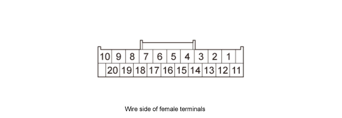 Courtesy of HONDA, U.S.A., INC. Courtesy of HONDA, U.S.A., INC.
|
| Cavity |
Wire Color |
Terminal Name |
Description |
| C1 |
GRY |
TELEM SIG SH |
Shield for terminals No. 2 and No. 12 |
| C2 |
YEL |
TELEM SIG- |
Inputs HFL prompts and telephone sound signal from HandsFreeLink control unit |
| C3 |
Not used |
Not used |
- - - |
| C4 |
YEL |
RS485- |
Communication signal to stereo amplifier |
| C5 |
BRN |
RS485+ |
Communication signal to stereo amplifier |
| C6 |
YEL |
AUX GND |
Ground for auxiliary jack assembly |
| C7 |
GRY |
AUX SH |
Shield for terminals No. 8, No. 17, and No. 18 |
| Cavity |
Wire Color |
Terminal Name |
Description |
| C8 |
BLK |
AUX SIG GND |
Ground for sound signal from auxiliary jack assembly |
| C9 |
PNK |
COMPASS 1 |
Communication signal to electrical compass unit |
| C10 |
ORN |
COMPASS 2 |
Communication signal to electrical compass unit |
| C11 |
Not used |
Not used |
- - - |
| C12 |
BRN |
TELEM SIG+ |
Inputs HFL prompts and telephone sound signal from HandsFreeLink control unit |
| C13 |
Not used |
Not used |
- - - |
| C14 |
Not used |
Not used |
- - - |
| C15 |
GRY |
RS485 SH |
Shield for terminals No. 4 and No. 5 |
| C16 |
PUR |
AUX DET |
Detects connection signal for auxiliary jack assembly |
| C17 |
WHT |
AUX RCH |
Inputs sound signal from auxiliary jack assembly |
| C18 |
RED |
AUX LCH |
Inputs sound signal from auxiliary jack assembly |
| C19 |
BLU |
COMPASS 3 |
Communication signal to electrical compass unit |
| C20 |
GRN |
COMPASS 4 |
Communication signal to electrical compass unit |
AUDIO UNIT CONNECTOR D (12P)
 Courtesy of HONDA, U.S.A., INC. Courtesy of HONDA, U.S.A., INC.
|
| Cavity |
Wire Color |
Terminal Name |
Description |
| D1 |
YEL |
GA BUS - |
GA-Net bus communication signal |
| D2 |
GRY |
GA BUS SH |
Shield for terminals No. 1 and No. 7 |
| D3 |
RED |
GA AUDIO L- |
Inputs sound signal from HandsFreeLink control unit and XM receiver |
| D4 |
WHT |
GA AUDIO R- |
Inputs sound signal from HandsFreeLink control unit and XM receiver |
| D5 |
GRY |
GA AUDIO SH |
Shield for terminals No. 3, No. 4, No. 9, and No. 10 |
| D6 |
PUR |
GND |
GA-Net related units ground |
| D7 |
BRN |
GA BUS + |
GA-Net bus communication signal |
| D8 |
ORN |
GA SYS ON |
Output signal for GA-Net related units switching on/off |
| D9 |
BLK |
GA AUDIO L+ |
Inputs sound signal from HandsFreeLink control unit and XM receiver |
| D10 |
GRN |
GA AUDIO R+ |
Inputs sound signal from HandsFreeLink control unit and XM receiver |
| D11 |
Not used |
Not used |
- - - |
| Cavity |
Wire Color |
Terminal Name |
Description |
| D12 |
BLU |
GA +B |
Outputs power source for GA-Net related units |
AUDIO UNIT CONNECTOR E (5P)
 Courtesy of HONDA, U.S.A., INC. Courtesy of HONDA, U.S.A., INC.
|
| Cavity |
Wire Color |
Terminal Name |
Description |
| E1 |
GRY |
TUNE SH |
Shield for terminals No. 2, No. 3, No. 4, and No. 5 |
| E2 |
RED |
TUNE L- |
Inputs sound signal from tuner unit |
| E3 |
BLK |
TUNE L+ |
Inputs sound signal from tuner unit |
| E4 |
WHT |
TUNE R- |
Inputs sound signal from tuner unit |
| E5 |
GRN |
TUNE R+ |
Inputs sound signal from tuner unit |
AUDIO UNIT CONNECTOR F (18P)
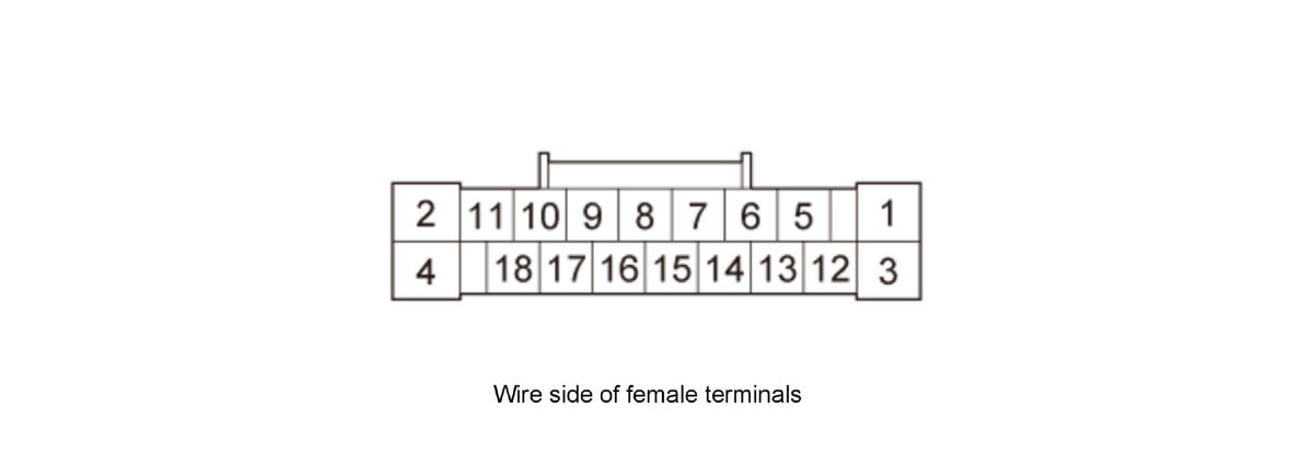 Courtesy of HONDA, U.S.A., INC. Courtesy of HONDA, U.S.A., INC.
|
| Cavity |
Wire Color |
Terminal Name |
Description |
| F1 |
BLK |
SGND |
Ground for audio unit (G505) |
| F2 |
Not used |
Not used |
- - - |
| F3 |
ORN |
+B RADIO |
Continuous power source |
| F4 |
Not used |
Not used |
- - - |
| F5 |
Not used |
Not used |
- - - |
| F6 |
Not used |
Not used |
- - - |
| Cavity |
Wire Color |
Terminal Name |
Description |
| F7 |
Not used |
Not used |
- - - |
| F8 |
Not used |
Not used |
- - - |
| F9 |
GRN |
JOG SH |
Shield for terminals No. 16 |
| F10 |
Not used |
Not used |
- - - |
| F11 |
Not used |
Not used |
- - - |
| F12 |
Not used |
Not used |
- - - |
| F13 |
Not used |
Not used |
- - - |
| F14 |
Not used |
Not used |
- - - |
| F15 |
Not used |
Not used |
- - - |
| F16 |
BLU |
JOG |
Input center switch panel/interface dial operation signal |
| F17 |
Not used |
Not used |
- - - |
| F18 |
Not used |
Not used |
- - - |
AUDIO UNIT CONNECTOR G (24P)
 Courtesy of HONDA, U.S.A., INC. Courtesy of HONDA, U.S.A., INC.
|
| Cavity |
Wire Color |
Terminal Name |
Description |
| G1 |
Not used |
Not used |
- - - |
| G2 |
GRY |
RR CAM SH |
Shield for terminals No. 3 and No. 15 |
| G3 |
YEL |
RR CAM RC GND |
Ground for video signal |
| G4 |
Not used |
Not used |
- - - |
| G5 |
BRN |
BIT 0 |
Mode select signal for rearview camera |
| G6 |
Not used |
Not used |
- - - |
| G7 |
Not used |
Not used |
- - - |
| G8 |
Not used |
Not used |
- - - |
| G9 |
Not used |
Not used |
- - - |
| G10 |
Not used |
Not used |
- - - |
| G11 |
Not used |
Not used |
- - - |
| G12 |
Not used |
Not used |
- - - |
| G13 |
Not used |
Not used |
- - - |
| G14 |
Not used |
Not used |
- - - |
| G15 |
BRN |
RR CAM VID |
Video signal for rearview camera |
| G16 |
WHT |
RR CAM VCC |
Power source for rearview camera |
| G17 |
RED |
RR CAM ADPT |
Detects connection signal for rearview camera |
| G18 |
ORN |
BIT 1 |
Mode select signal for rearview camera |
| Cavity |
Wire Color |
Terminal Name |
Description |
| G19 |
Not used |
Not used |
- - - |
| G20 |
Not used |
Not used |
- - - |
| G21 |
Not used |
Not used |
- - - |
| G22 |
Not used |
Not used |
- - - |
| G23 |
Not used |
Not used |
- - - |
| G24 |
BRN |
BACK LT |
Reverse signal of select lever from reverse relay circuit |
AUDIO UNIT CONNECTOR J (5P)
 Courtesy of HONDA, U.S.A., INC. Courtesy of HONDA, U.S.A., INC.
|
| Cavity |
Wire Color |
Terminal Name |
Description |
| J1 |
- - - |
USB GND |
Ground for communication signal |
| J2 |
- - - |
USB VBUS |
Outputs power source for USB device |
| J3 |
- - - |
USB DATA+ |
Communication signal for HandsFreeLink control unit |
| J4 |
- - - |
USB DATA- |
Communication signal for HandsFreeLink control unit |
| J5 |
- - - |
USB SH |
Shield for terminals No. 1, No. 2, No. 3, and No. 4 |
AUDIO UNIT CONNECTOR K (5P)
 Courtesy of HONDA, U.S.A., INC. Courtesy of HONDA, U.S.A., INC.
|
| Cavity |
Wire Color |
Terminal Name |
Description |
| K1 |
- - - |
USB GND |
Ground for communication signal |
| K2 |
- - - |
USB VBUS |
Outputs power source for USB device |
| K3 |
- - - |
USB DATA+ |
Communication signal |
| K4 |
- - - |
USB DATA- |
Communication signal |
| K5 |
- - - |
USB SH |
Shield for terminals No. 1, No. 2, No. 3, and No. 4 |
AUDIO UNIT CONNECTOR L (3P)
 Courtesy of HONDA, U.S.A., INC. Courtesy of HONDA, U.S.A., INC.
|
| Cavity |
Wire Color |
Terminal Name |
Description |
| L1 |
- - - |
GVIF- |
Outputs video signal for center display unit |
| L2 |
- - - |
GVIF+ |
Outputs video signal for center display unit |
| L3 |
- - - |
GVIF SH |
Shield for terminals No. 1 and No. 2 |