Oil Pan Removal
- If the engine is out of the vehicle, go to step 18.
- Raise the vehicle on the lift to full height.
- Drain the engine oil (see
ENGINE OIL REPLACEMENT
).
- Remove the front wheels.
- Remove the splash shield (see step 26 on
ENGINE REMOVAL
).
- Separate the stabilizer links (see
STABILIZER LINK REMOVAL/INSTALLATION
).
- Separate the knuckles from the lower arms (see
KNUCKLE/HUB/WHEEL BEARING REPLACEMENT
).
- Remove the steering gearbox bracket. Remove the steering gearbox mounting bolt, stiffener mounting bolt, and stiffener (see step 37 on
ENGINE REMOVAL
).
- Remove the steering gearbox mounting bolt, stiffener mounting bolt, and stiffener. Remove the harness clamp from the front subframe (see step 39 on
ENGINE REMOVAL
).
- A/T model: Remove the bolt securing the automatic transmission fluid (ATF) filter.
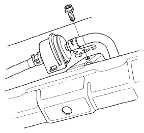 Courtesy of AMERICAN HONDA MOTOR CO., INC.
- Install the front leg assembly, the hook, and the wing nut to an A and Reds engine support hanger (AAR-T1256) onto the 2006 Civic engine hanger (VSB02C000025). Carefully position the engine hanger on the vehicle, and attach the hook to the slotted hole in the support eyelet. Tighten the wing nut by hand to lift and support the engine/ transmission (see step 47 on ENGINE REMOVAL
).
- Remove the lower torque rod (see step 50 on
ENGINE REMOVAL
).
- M/T model: Remove the front mount mounting bolt (see step 51 on
ENGINE REMOVAL
).
- Note the reference marks on the both sides of the front subframe that line up with the body (see step 52 on
ENGINE REMOVAL
).
- Loosen the front subframe body mount bracket mounting bolts on both sides (see step 53 on
ENGINE REMOVAL
).
- Attach the front subframe adapter (VSB02C000016) to the subframe by looping the strap over the front of the subframe, then secure the strap with the stop, then tighten the wing nut. Raise the jack and line up the slots in the arms with the bolt holes on the corner of the jack base, then tighten the bolts (see step 54 on
ENGINE REMOVAL
).
- Remove the front subframe (see step 56 on
ENGINE REMOVAL
).
- Remove the lower torque rod bracket.
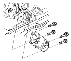 Courtesy of AMERICAN HONDA MOTOR CO., INC.
- A/T model: Remove the shift cable cover.
 Courtesy of AMERICAN HONDA MOTOR CO., INC.
- K20Z2: Remove the torque converter cover/clutch cover.
 Courtesy of AMERICAN HONDA MOTOR CO., INC.
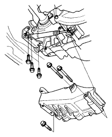
- K2023: Remove the clutch cover (A) and transmission mounting bolts (B).
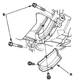 Courtesy of AMERICAN HONDA MOTOR CO., INC.
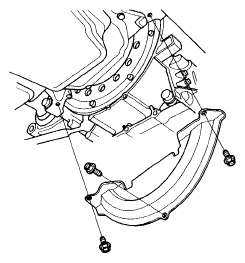
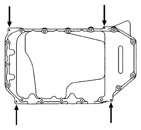
- Remove the bolts securing the oil pan.
- Using a flat blade screwdriver, separate the oil pan from the block in the places shown.
 Courtesy of AMERICAN HONDA MOTOR CO., INC.
- Remove the oil pan.