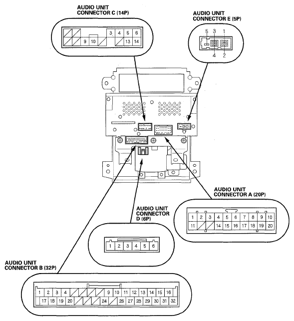
Audio Unit Connector for Inputs and Outputs
When replacing an audio unit connector, match the wires to the cavities listed in the following tables.
 Courtesy of AMERICAN HONDA MOTOR CO., INC.
AUDIO UNIT CONNECTOR A (20P)
WIRE CAVITY CHART
| Cavity |
Wire |
Connects to |
| A1 |
WHT |
RADIO SW (+B) |
| A2 |
PUR |
Audio power supply |
| A3 |
ORN |
Audio remote switch |
| A4 |
BRN |
Display panel control unit (NAVI SCTY) |
| A5 |
BLU |
Stereo amplifier (RR R+) |
| A6 |
PUR |
Stereo amplifier (RR L+) |
| A7 |
GRN |
Stereo amplifier (FR R+) |
| A8 |
WHT |
Stereo amplifier (FR L+) |
| A9 |
LTBLU |
Lights-on signal (ILL+) |
| A10 |
WHT |
Constant power (+B) |
| A11 |
BRN |
Audio remote switch ground |
| A14 |
GRY |
Stereo amplifier (PRE AMP shield) |
| A15 |
ORN |
Stereo amplifier (RR R-) |
| A16 |
YEL |
Stereo amplifier (RR L-) |
| A17 |
BLK |
Stereo amplifier (FR R-) |
| A18 |
RED |
Stereo amplifier (FR L-) |
| A19 |
ORN |
Dash lights brightness controller (ILL-) |
| A20 |
BRN
BLK |
Ground (G504) |
AUDIO UNIT CONNECTOR B (32P)
WIRE CAVITY CHART
| Cavity |
Wire |
Connects to |
| B1 |
BRN |
Stereo amplifier (FR CTR+) |
| B2 |
PNK |
Stereo amplifier (SUB+) |
| B3 |
GRY |
Stereo amplifier (BOSE BUS shield) |
| B4 |
GRN |
Stereo amplifier (BOSE BUS+) |
| B8 |
GRN |
OnStar control unit (TELEMA MUTE) |
| B9 |
RED |
XM receiver (HP MUTE) |
| B10 |
RED |
Climate control unit (CLK-AC) |
| B11 |
ORN |
Smart ECU (IMS 1) |
| B12 |
PNK |
Audio subdisplay unit (ACC) |
| B13 |
GRN |
Audio subdisplay unit (BLANK) |
| B14 |
YEL |
Audio subdisplay unit (CLOCK) |
| B15 |
RED |
Audio subdisplay unit (LOAD) |
| B16 |
BLU |
Audio subdisplay unit (LCD BL+) |
| B17 |
LTGRN |
Stereo amplifier (FR CTR-) |
| B18 |
LTBLU |
Stereo amplifier (SUB-) |
| B19 |
GRY |
Stereo amplifier (AMP shield) |
| B20 |
RED |
Stereo amplifier (BOSE BUS-) |
| B24 |
LTGRN |
Handsfreelink control unit (HFT MUTE) |
| B26 |
YEL |
Climate control unit (SQ-AC) |
| B27 |
PNK |
Keyless access control unit(IMS2) |
| B28 |
PUR |
Audio subdisplay unit (5VGND) |
| B29 |
GRY |
Audio subdisplay unit (Shield) |
| B30 |
BLK |
Audio subdisplay unit (SEG TEST) |
| B31 |
WHT |
Audio subdisplay unit (DATA) |
| B32 |
ORN |
Audio subdisplay unit (LCD BL-) |
AUDIO UNIT CONNECTOR C (14P)
WIRE CAVITY CHART
| Cavity |
Wire |
Connects to |
| C2 |
PUR |
XM receiver (SAT SYS ACC) |
| C3 |
GRY |
AcuraLink control unit (XM receiver) or XM receiver (BUS (GA-NET) shield) |
| C4 |
GRY |
AcuraLink control unit (XM receiver) or XM receiver (HP shield) |
| C5 |
GRN |
AcuraLink control unit (XM receiver) or XM receiver (HP R+) |
| C6 |
WHT |
AcuraLink control unit (XM receiver) or XM receiver (HP L+) |
| C9 |
GRN |
AcuraLink control unit (XM receiver) or XM receiver (BUS+ (GA-NET)) |
| C10 |
RED |
AcuraLink control unit (XM receiver) or XM receiver (BUS- (GA-NET)) |
| C13 |
BLK |
AcuraLink control unit (XM receiver) or XM receiver (HP R-) |
| C14 |
RED |
AcuraLink control unit (XM receiver) or XM receiver (HP L-) |
AUDIO UNIT CONNECTOR D (6P) ('07 model)
WIRE CAVITY CHART
| Cavity |
Wire |
Connects to |
| D1 |
YEL |
Auxiliary jack assembly (AUX DET) |
| D2 |
BLK |
Auxiliary jack assembly (AUX GND) |
| D3 |
RED |
Auxiliary jack assembly (AUX R-CH) |
| D4 |
GRN |
Auxiliary jack assembly (AUX SIG GND) |
| D5 |
WHT |
Auxiliary jack assembly (AUX L-CH) |
| D6 |
GRY |
Auxiliary jack assembly (AUX SH GND) |
AUDIO UNIT CONNECTOR E (5P)
WIRE CAVITY CHART
| Cavity |
Wire |
Connects to |
| 1 |
-- |
AM/FM subantenna amplifier (SIG) |
| 2 |
-- |
AM/FM subantenna amplifier (SH (AM/FM)) |
| 3 |
-- |
AM/FM main antenna amplifier (SIG) |
| 4 |
-- |
AM/FM main antenna amplifier (SH (AM/FM)) |
| 5 |
-- |
AM/FM antenna amplifier (SWD+B) |