Vehicle Speed Signal Circuit
- Check fuse No. 9 (10-amp) located in driver's underdash fuse/relay box. If fuse is blown, locate and repair problem in wiring or components connected to fuse No. 9, then retest cruise control operation. See POWER DISTRIBUTION
article in WIRING DIAGRAMS. If problem does not exist, go to next step.
- Remove instrument panel cluster. See REMOVAL & INSTALLATION
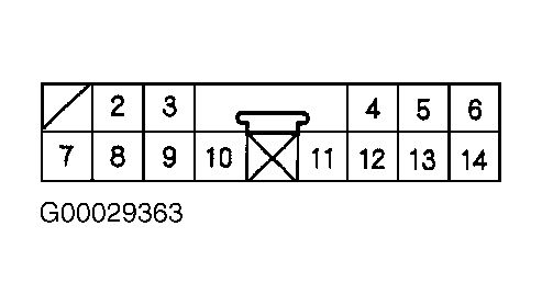
in INSTRUMENT PANELS - MDX article. Using DVOM, check for continuity between ground and instrument panel cluster harness connector "C" terminals No. 9 and 10 (Black wires). See Fig 1. If either circuit does not have continuity to ground, locate and repair open in Black wire between instrument panel cluster and ground G501. See COMPONENT LOCATIONS . If both circuits have continuity to ground, go to next step.
- Disconnect instrument panel cluster harness connector "C". Raise and support vehicle. Put vehicle in neutral. Backprobing, connect positive probe of DVOM to instrument panel cluster harness connector "C" terminal No. 2 (Blue/White wire). See Fig 1. Connect negative probe of DVOM to ground. Turn ignition on. Go to next step.
- Block one wheel and slowly rotate other wheel over 3 MPH. As wheel is rotated, voltage should repeatedly pulse from zero volts to about 5 volts. If voltage pulses as specified, replace instrument panel cluster. See REMOVAL & INSTALLATION
in INSTRUMENT PANELS article. If voltage pulses are not as specified, go to next step.
- Turn ignition off. Backprobing, connect positive probe of DVOM to PCM 32-pin connector "A" terminal No. 9 (Blue/White wire). See Figure. Connect negative probe of DVOM to ground. Turn ignition on. Block one wheel and slowly rotate other wheel over 3 MPH. As wheel is rotated, voltage should repeatedly pulse from zero volts to about 5 volts. If voltage pulses as specified, repair open circuit in Blue/White wire between PCM and instrument panel cluster. See WIRING DIAGRAMS . If voltage pulses are not as specified, go to next step.
- Disconnect PCM 32-pin connector "A". Check continuity between ground and PCM connector "A" terminal No. 9 (Blue/White wire). If continuity exists, repair short to ground in Blue/White wire between PCM, instrument panel cluster, driver's multiplex control unit or cruise control unit. See WIRING DIAGRAMS . If continuity does not exist, check connectors for loose, damaged or corroded terminals. If problem exists, repair connector. If problem does not exist, replace PCM with known-good PCM and retest system.
 Courtesy of AMERICAN HONDA MOTOR CO., INC.