DTC 6-1: Front Fail-Safe Relay Malfunction
- Start engine. If ABS indicator light goes out, system has returned to normal. Check wiring between fail-safe relays, ABS control unit and solenoids for intermittent short to power. See WIRING DIAGRAMS
. If ABS indicator light stays on, verify DTC. If a code other than DTC 6-1 sets, see appropriate DTC. If DTC 6-1 resets, test front fail-safe relay. See ABS FAIL-SAFE RELAY & GAUGE RELAY TEST under DIAGNOSIS & TESTING
. Replace relay as necessary. If relay tests okay, go to next step.
- Disconnect ABS modulator unit 14-pin connector. Visually inspect ABS modulator unit harness. Repair harness as necessary. If harness checks okay, start engine. Using DVOM, measure voltage between ground and front fail-safe relay connector terminal No. 3 (Brown/Black wire). See Fig 1
. If battery voltage does not exist, go to next step. If battery voltage exists, repair short to power in Brown/Black wire between ABS modulator unit and front fail-safe relay. See WIRING DIAGRAMS
.
- Turn ignition off. Disconnect ABS control unit 26-pin connector. Start engine. Measure voltage between ground and ABS control unit 26-pin connector terminal No. 2 (Red/Black wire). See Figure
. If battery voltage does not exist, go to next step. If battery voltage exists, repair short to power in Red/Black wire between ABS control unit and ABS modulator unit. See WIRING DIAGRAMS
.
- Measure voltage between ground and ABS control unit 26-pin connector terminal No. 1 (Red/Blue wire). See Figure
. If battery voltage does not exist, go to next step. If battery voltage exists, repair short to power in Red/Blue wire between ABS control unit and ABS modulator unit. See WIRING DIAGRAMS
.
- Measure voltage between ground and ABS control unit 26-pin connector terminal No. 15 (Yellow/Black wire). See Figure
. If battery voltage does not exist, go to next step. If battery voltage exists, repair short to power in Yellow/Black wire between ABS control unit and ABS modulator unit. See WIRING DIAGRAMS
.
- Measure voltage between ground and ABS control unit 26-pin connector terminal No. 14 (Yellow/Blue wire). See Figure
. If battery voltage does not exist, check for poor connection at ABS control unit. If connection is okay, replace ABS control unit. If battery voltage exists, repair short to power in Yellow/Blue wire between ABS control unit and ABS modulator unit. See WIRING DIAGRAMS
.
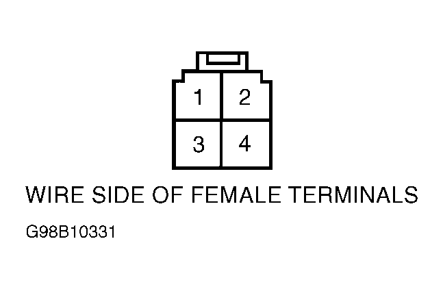 Courtesy of AMERICAN HONDA MOTOR CO., INC.